A combined twin-shaft continuous mixer

A twin-horizontal shaft, combined technology, used in cement mixing devices, raw material supply devices for sale, clay preparation devices, etc., can solve problems such as the deterioration of the stiffness of the mixing shaft, the reduction of the reliability of the machine, the reduction of the residence time of the stirring speed, and the increase of the The effect of stirring time, eliminating stirring dead zone and improving stirring uniformity

Inactive Publication Date: 2016-11-09
CHANGAN UNIV
View PDF4 Cites 0 Cited by
  • Summary
  • Abstract
  • Description
  • Claims
  • Application Information

AI Technical Summary

Problems solved by technology

The simplest method is to directly increase the overall length of the mixing drum, but at the same time, the rigidity of the stirring shaft will deteriorate sharply, which will easily cause a series of problems such as deformation of the stirring shaft, excessive bearing load, and reduced reliability of the machine; some use two Two-stage stirring of an independent mixer, but this method complicates the mixing equipment, increases the space occupied by the mixing equipment and equipment cost; some reduce the stirring speed to increase the residence time of the stabilized soil material in the mixing drum, but This method will simultaneously cause a decrease in the circumferential speed of the mixing, thereby reducing the effect of the forced mixing of the stabilized soil material along the vertical and transverse directions of the mixing drum, and will still lead to poor uniformity of the produced stabilized soil material
[0004] At the same time, the existing twin-shaft continuous mixer generally adopts a structure without a liner. During the production process, the stabilized soil material will adhere to the inner wall of the mixing drum. Although it can form a certain protection for the drum wall during mixing, the The cleaning of this layer of adhesive material after production is time-consuming and laborious

Method used


Image

  • A combined twin-shaft continuous mixer
  • A combined twin-shaft continuous mixer
  • A combined twin-shaft continuous mixer

Examples


Embodiment Construction

[0029] Below in conjunction with accompanying drawing, the present invention is described in further detail:

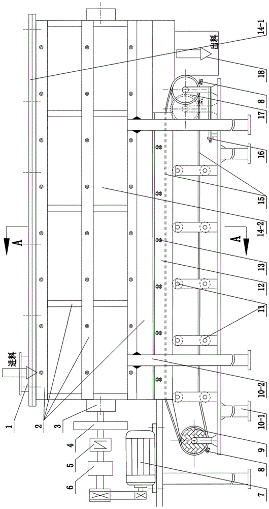
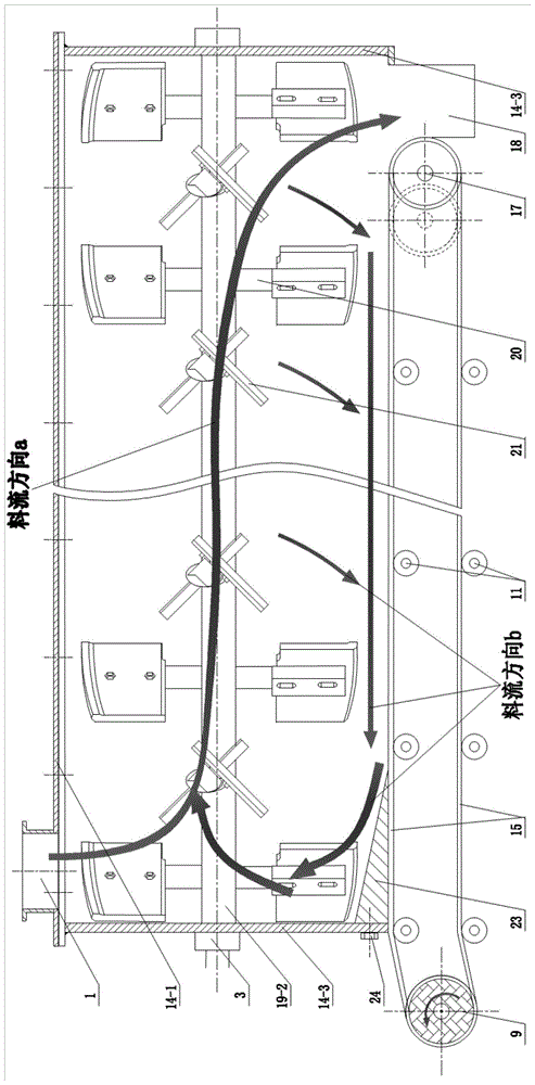
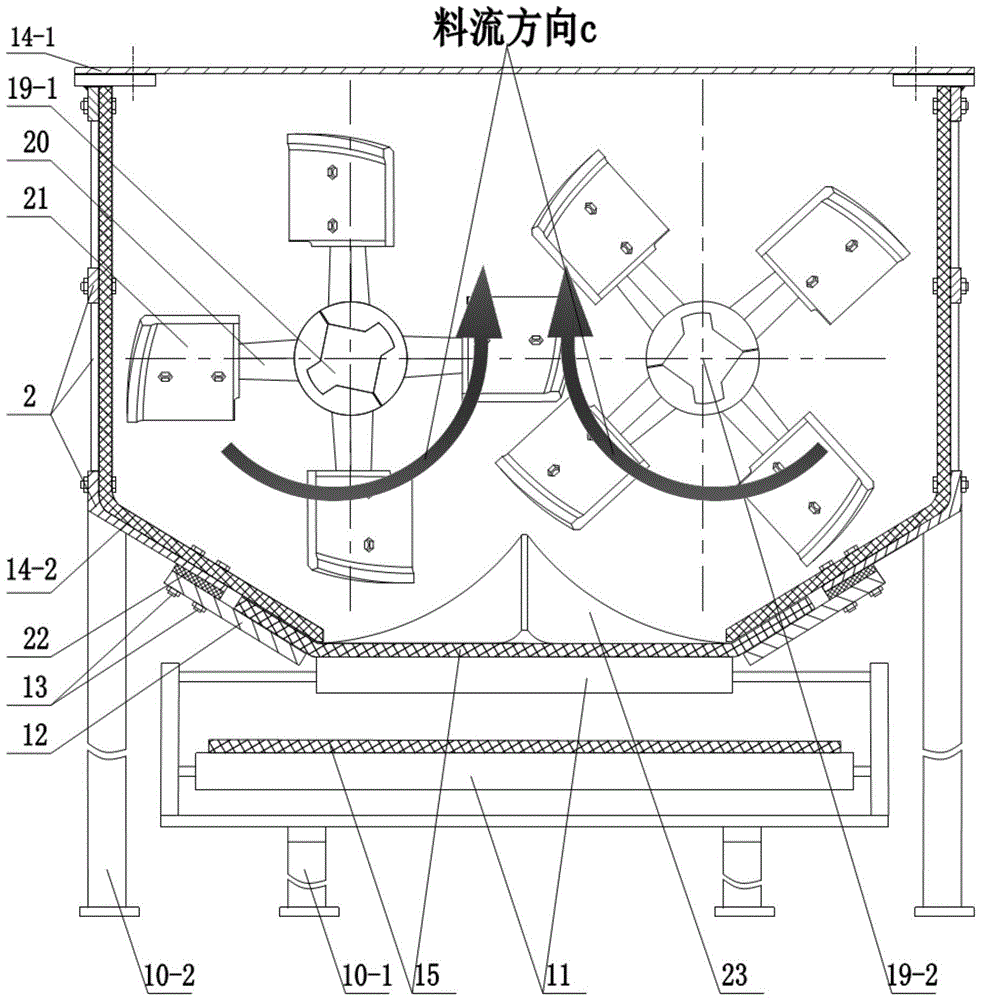
[0030] see Figure 1 to Figure 5 , a combined twin-shaft continuous mixer, including a mixing main structure and a conveyor belt structure, the main mixing structure includes a mixing drum, and the mixing drum includes a mixing drum upper cover 14-1, a mixing drum side plate 14-3 and several L-shaped The mixing drum lining plate 14-2, the front and back of the mixing drum are spliced ​​by 4 L-shaped mixing drum lining plates 14-2, the end faces on both sides are the mixing drum side plates 14-3, and the top surface is the mixing drum liner plate 14-2. The upper cover of the drum 14-1; the outer side of the mixing drum is provided with a structural frame 2, the L-shaped mixing drum liner 14-2 is fixed on the structural frame 2 by bolts, and the side plate of the mixing drum 14-3 is connected to the structural frame 2 by welding On, the upper cover 14-1 of the mixing d...


PUM


Abstract

The invention discloses a combined twin-shaft continuous mixer, which comprises a main mixing structure and a conveyor belt structure, the main mixing structure includes a mixing drum, the mixing drum is supported by a mixing drum frame arranged on it, and the top of the mixing drum is provided with There is a material inlet and a discharge port at the bottom. Two stirring shafts are arranged side by side inside the mixing drum. The stirring units on the two stirring shafts are arranged alternately. One side of the mixing drum is equipped with power and its transmission structure. The conveyor belt structure is designed In the lower part of the mixing drum, the conveyor belt structure includes a conveyor belt, a driving drum that can rotate clockwise or counterclockwise and can be tuned to provide power for the conveyor belt, and a guide roller that acts as a guide. The conveyor belt also serves as the bottom surface of the mixing drum. The bottom of the mixing drum of the present invention is composed of a movable conveying belt to adjust the flow characteristics of the stabilized soil material in the mixing drum, effectively increase the time for the stabilized soil material to be stirred in the mixing drum, thereby increasing the uniformity of stirring of the stabilized soil.

Description

technical field [0001] The invention belongs to the field of stabilized soil material mixers, and relates to a continuous mixer, in particular to a combined twin-shaft continuous mixer for producing stabilized soil materials. Background technique [0002] Twin-shaft continuous mixer, as the core working device widely used in stabilized soil plant mixing equipment, determines the mixing quality and efficiency of finished stabilized soil and other pavement base materials. This kind of mixer mainly uses the motor to drive the mixing unit (stirring shaft, stirring arm, stirring blade) to rotate in the mixing drum to realize continuous forced stirring of the pavement base material. Since the stabilized soil material has the characteristics of continuous feeding, continuous mixing and continuous discharge during work, the length of the mixing drum of the continuous twin-shaft mixer is limited, and the residence time (time to be stirred) of the stabilized soil material in the mixin...

Claims


Application Information

Patent Timeline
Patent Type & Authority Patents(China)
IPC IPC(8): B28C5/14
CPCB28C5/146B28C7/06
Inventor 赵利军刘云飞徐超蒋文志
Owner CHANGAN UNIV
Why Eureka
Try Eureka