Elevator control device

An elevator control device and elevator system technology, applied in the field of elevator control devices, can solve problems such as lack of clear and accurate calculation means, difficulty in implementation, and difficulty in suppressing or eliminating

Active Publication Date: 2015-05-27
SHANGHAI MITSUBISHI ELEVATOR CO LTD
View PDF8 Cites 22 Cited by
  • Summary
  • Abstract
  • Description
  • Claims
  • Application Information

AI Technical Summary

Problems solved by technology

[0006] Second, the vibration of the car is difficult to suppress or eliminate due to the weak coupling between the motor and the car; in recent years, with the increase of the lift height of the elevator, the vibration problem of the car when it starts on a lower floor has become more and more prominent
But this directly leads to higher cost and increased system weight
It is not economical to configure the suspension device much higher than the required specification for load-bearing in order to alleviate the start-up vibration
Moreover, this is only passive mitigation, rather than suppressing the starting vibration from the source
[0008] Chinese patents CN1221701A and CN1158817A disclose methods for compensating car vibrations, and they have two things in common: first, they all perform passive compensation when car vibrations occur, and do not care about the source of the vibrations; therefore , these methods can only alleviate the vibration to a limited extent, and it is impossible to complete

Method used


Image

  • Elevator control device
  • Elevator control device
  • Elevator control device

Examples


Embodiment 1

[0142] The positive and negative signs that define the current value of the motor. The positive sign indicates that the torque generated by the current makes the car obtain upward acceleration; the negative sign indicates that the torque generated by the current makes the car obtain downward acceleration;

[0143] Define the positive direction of displacement as the upward direction of the car;

[0144] The sampling period used by the control device is 5ms;

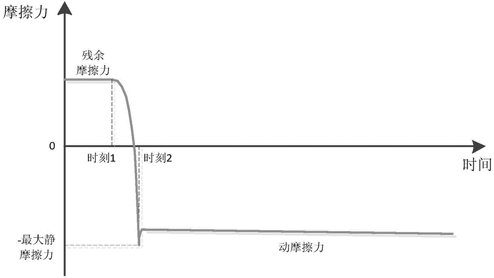
[0145] When residual friction force estimation is required (it can be triggered manually or automatically by the control device, not shown in the figure), the control device enters the residual friction force estimation mode; in this mode, the speed command generation unit issues a specific speed Command to direct the car to run to the same floor in the upward and downward directions; the residual friction estimation part reads the speed command, motor motion state feedback signal and brake action signal (not shown in the figure...

Embodiment 2

[0200] Compared with the embodiment 1, the method of estimating the residual friction is different in this embodiment; the other parts are the same;

[0201] When estimating the residual friction force, when the car is at no load, half load and full load, use the formula (4) described in Example 1 to calculate the residual friction currents corresponding to the three loads:

[0202] I rf_N ……No-load residual friction current

[0203] I rf_B ……Half-load residual friction current

[0204] I rf_F ……Full load residual friction current

[0205] When the system is working normally, assuming that the ratio of the load in the car to the full load value is p, if the car was going up last time, the residual friction current estimation method is:

[0206] I rf =(2I rf_F -4I rf_B +2I rf_N )p 2 +(-I rf_F +4I rf_B -3I rf_N )p+I rf_N Formula (20)

[0207] If the car was going down last time, the estimation method of residual friction current is:

[0208] I rf =-(2I rf_F -4I rf_B +2I rf_N )...

Embodiment 3

[0210] In this embodiment, the method for estimating the residual friction force is the same as that of Embodiment 1 or Embodiment 2; the method for estimating the maximum friction force is the same as that of Embodiment 1;

[0211] When the elevator system needs to be started, apply the pre-energized current I according to the formula (7) described in embodiment 1 pre ;

[0212] Then the control device drives the brake to release and applies a specific speed command V pre , And enable the speed command follower; where V pre The smaller the value, the stronger the effect of suppressing the startup vibration; but V pre Too small will cause too long waiting time when the system starts; therefore, the above factors should be considered comprehensively to select V pre Value; here will V pre Take 0.05m / s, and its direction is the current running direction of the car;

[0213] At this time, the current I applied to the motor is:

[0214] I=I wgh +I rf-l +I cont Formula (22)

[0215]...


PUM


Abstract

The invention discloses an elevator control device. The elevator control device comprises a speed command generating part, a speed command following part, a load torque calculating part, and a current command following part; the device generates and tracks a speed command of lift car running and a current command of an electric motor, so that the elevator system is ran. The elevator control device further comprises a residual frictional force estimating part, which is used for estimating the static frictional force suffered by the elevation system after stopping; a maximum frictional force estimating part, which is used for estimating the maximum static frictional force suffered by the elevator system; an offset torque calculating part, which is used for calculating the offset torque according to the estimated residual frictional force and the maximum frictional force, wherein initial value of the offset torque is calculated according to the estimated residual frictional force, and the target value of the offset torque is calculated according to the maximum frictional force obtained through estimation and the running direction of the lift car this time. Through calculation and application of offset torque, the elevator control device can be more simply and effectively inhibit the vibration of the lift car in the course of vibration.

Description

Technical field [0001] The invention relates to an elevator control device. Background technique [0002] For traction drive elevators or forced drive elevator systems, when the car starts, it is inevitably subjected to mechanical friction. The composition of the traction drive elevator system is as figure 1 As shown, the elevator control device includes a speed command generating part, a speed command following part, a load torque calculation part and a current command following part (not shown in the figure). The elevator car using this elevator control device vibrates when it starts. [0003] The following is an example of behavior on the car to illustrate the mechanism of car vibration during startup. Before the brake is released, the car is affected by the residual friction; the residual friction refers to the friction that is produced by the elasticity of the suspension and the friction of the mechanical system. The direction of the last operation of the system is related....

Claims


Application Information

Patent Timeline
IPC IPC(8): B66B1/30
CPCB66B1/304B66B2201/00
Inventor 钱敏陈玉东刘玉兵
Owner SHANGHAI MITSUBISHI ELEVATOR CO LTD
Why Eureka
Try Eureka