
A double-suction centrifugal fan

A centrifugal fan, double-suction technology, used in mechanical equipment, non-variable-capacity pumps, machines/engines, etc., can solve the problems of complicated internal flow conditions and reduced fan performance in centrifugal fans, and achieve improved static pressure- Effect of flow characteristics, improved aerodynamic performance, enhanced stability

Inactive Publication Date: 2017-04-05
ZHEJIANG SCI-TECH UNIV +1
View PDF6 Cites 0 Cited by
  • Summary
  • Abstract
  • Description
  • Claims
  • Application Information

AI Technical Summary

Problems solved by technology

In practical applications, the flow inside the centrifugal fan is very complicated, especially when the centrifugal fan operates under partial load, there will be unsteady flow, and the performance of the fan will be significantly reduced with the generation of unsteady flow
Although my country's centrifugal fan industry has achieved tremendous development in recent years, there is still a large gap compared with foreign advanced enterprise technology.

Method used


Image

  • A double-suction centrifugal fan
  • A double-suction centrifugal fan
  • A double-suction centrifugal fan

Examples


Embodiment Construction

[0017] The present invention will be further described below in conjunction with the accompanying drawings and embodiments.

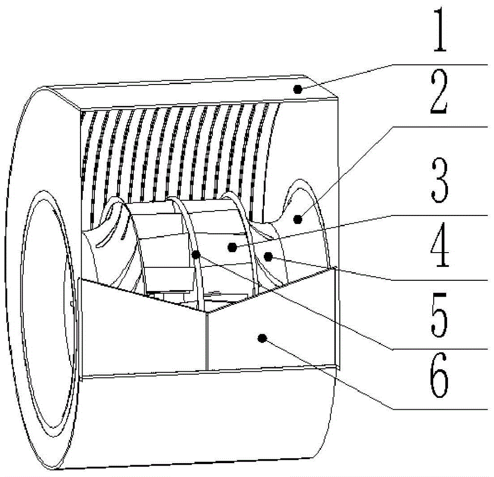
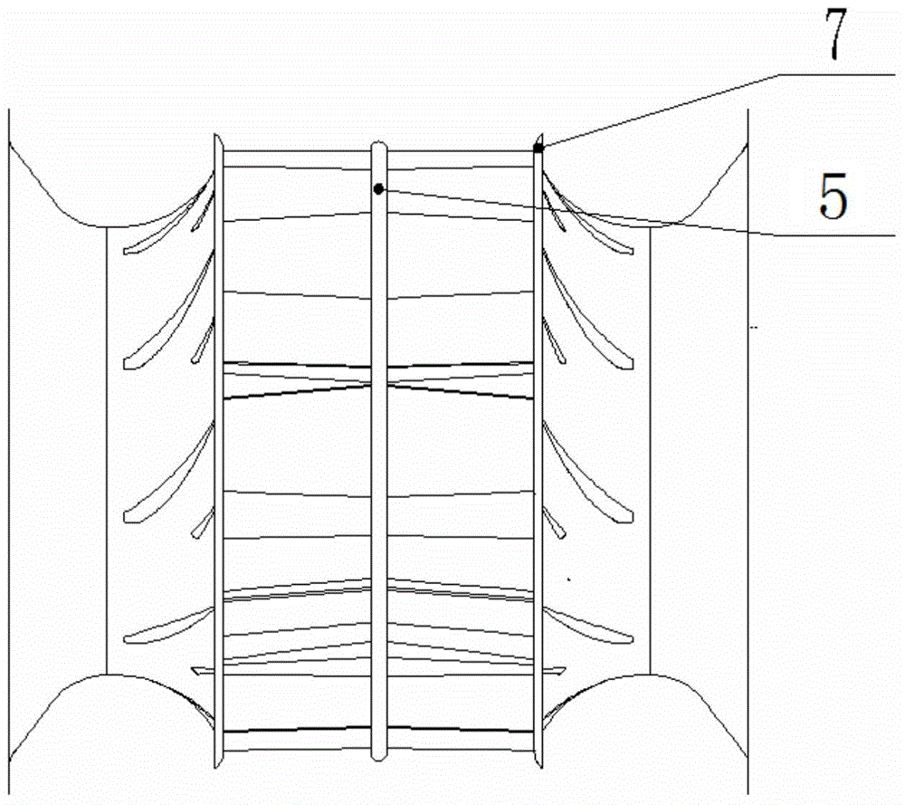
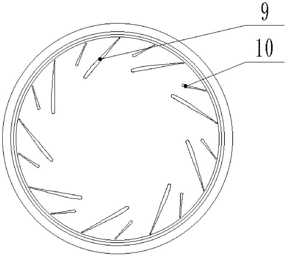
[0018] Such as figure 1 , 2 Shown in and 3, a double-suction centrifugal fan includes a volute 1, a front guide 2 and a double-suction impeller 3; the volute 1 is provided with a baffle 6 at the outlet; the double-suction impeller 3 includes a wheel cover 4. Wheel disc 5 and blade group; two blade groups are arranged symmetrically on both sides of the wheel disc 5; the blade group includes long blades 9 and short blades 10; nine long blades 9 are evenly distributed along the circumference, and two adjacent long blades 9 are provided with short blades 10; all short blades 10 are evenly distributed along the circumference; end welding; the outer ends of the two wheel covers 4 are welded with a front guide 2 respectively.

[0019] The edge of the welding end of wheel cover 4, long blade 9 and short blade 10 is provided with a bladeless diffuser edge 7; ...


PUM


Abstract

The invention discloses a double-suction type centrifugal ventilation fan. Centrifugal fan technologies in China still need to continue to improve, so as to enhance the stability of operation of fans, increase the efficiency of operation of the fans and lower the power consumption of the fans. According to the double-suction type centrifugal ventilation fan, a flow baffle is arranged at an outlet of a volute; two blade groups are symmetrically arranged at the two sides of a wheel disc; each blade group comprises a plurality of long blades and short blades; the long blades are uniformly distributed along the circumference, and a short blade is arranged between every two adjacent long blades; the inner end faces of the long and short blades are all welded to the wheel disc, and the outer end faces of the long and short blades are all welded to the inner ends of two wheel covers; the outer end of each of the two wheel covers is welded to a forward guider; bladeless pressure expanding edges are arranged at the edges of ends, welded to the long and short blades, of the wheel covers; the rim of the wheel disc is a spherical surface; a plurality of resistance reduction grooves which are equidistantly arranged along the axial direction of the wheel disc are formed in the internal sidewall of the volute. The double-suction type centrifugal ventilation fan has the advantages that the static pressure-flow characteristic and efficiency-flow characteristic of the existing double-suction type centrifugal ventilation fans can be improved, and thus, the pneumatic performance of the existing double-suction type centrifugal ventilation fans is improved.

Description

technical field [0001] The invention belongs to the field of ventilation equipment, and relates to a centrifugal fan, in particular to a double-suction centrifugal fan. Background technique [0002] In my country, gas transportation and gas compression machinery are collectively referred to as fans. Commonly referred to as fans include ventilators, blowers, compressors and Roots blowers. Fans are classified according to their internal air flow direction, and can be mainly divided into three types: axial flow, centrifugal and mixed flow (diagonal flow). Among them, the structure of the centrifugal fan is relatively simple, and it is widely used in environments that require ventilation, cooling, and dust removal, as well as drying and sorting grains. It can also provide wind sources for wind tunnel tests and be used as propulsion devices for hovercraft. [0003] Centrifugal fan is a general-purpose machine widely used in various industries of the national economy. As the do...

Claims


Application Information

Patent Timeline
Patent Type & Authority Patents(China)
IPC IPC(8): F04D29/42F04D29/28F04D29/30
CPCF04D29/28F04D29/30F04D29/4206F04D29/441
Inventor 窦华书张滨炜杨徽魏义坤陈小平姜陈锋陈永宁何海江应存列叶信学曹文斌
Owner ZHEJIANG SCI-TECH UNIV
Learn More