
Industrial waste steam condensing device

A condensing device and waste steam technology, applied in steam/steam condensers, lighting and heating equipment, etc., can solve the problems of breeding harmful bacteria, changing atmospheric pressure, heat waste, etc., to speed up the condensation speed, increase the contact area, avoid The effect of re-vaporization

Active Publication Date: 2015-05-27
长成新能股份有限公司
View PDF9 Cites 1 Cited by
  • Summary
  • Abstract
  • Description
  • Claims
  • Application Information

AI Technical Summary

Problems solved by technology

Nowadays, industrial waste steam is often discharged out of the working environment through underground ditch or tunnel. First, the waste steam is doped with harmful gas or dust, which will cause air pollution after being discharged. Secondly, the heat of waste steam is usually relatively high. It will increase the ambient temperature and change the atmospheric pressure; again, the waste steam will increase the air humidity and breed harmful bacteria; finally, the waste steam for industrial use contains heat, and the waste steam will cause waste of heat when discharged

Method used


Image

  • Industrial waste steam condensing device

Examples


Embodiment 1

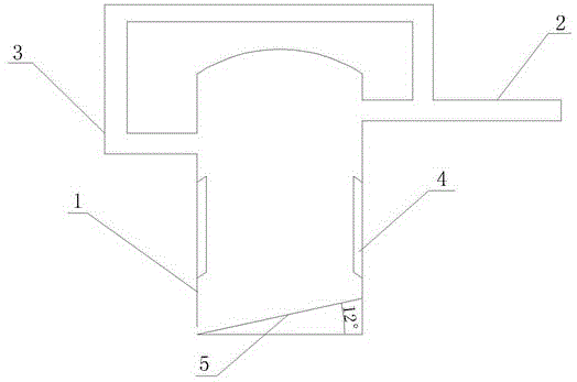
[0013] Example 1, such as figure 1 As shown, a waste steam condensing device provided in this embodiment includes a condensation chamber 1, a waste steam inlet pipe 2, a waste steam recovery pipe 3 and a water collection area 5, and a waste steam inlet pipe is connected to the inner wall of the condensation chamber 1 2. The inlet of the waste steam inlet pipe 2 collects the waste steam generated during the industrial operation. In contrast, the waste steam recovery pipe 3 is provided on the inner wall of the condensation chamber 1, the output port of the waste steam recovery pipe 3 communicates with the inlet of the waste steam inlet pipe 2, and the position of the waste steam recovery pipe 3 is lower than that of the waste steam The position of the inlet pipe 2 is favorable for the waste steam to be fully condensed in the condensation chamber 1 .

[0014] The water collection area 5 is located at the bottom of the condensation chamber 1, and the bottom of the water collectio...

Embodiment 2

[0015] Embodiment 2. The difference between this embodiment and Embodiment 1 is that the inside of the condensate 4 communicates with an external condensing device, and the condensing device cools the air in the condensate 4 to cool the waste steam.


PUM


Abstract

The invention discloses an industrial waste steam condensing device. The industrial waste steam condensing device comprises a condensation chamber, a waste steam inlet pipe, a waste steam recovery pipe and a water collection area. The inner wall of the condensation chamber is connected to the waste stream inlet pipe and provided with the waste steam recovery pipe. The water collection area is arranged at the bottom of the condensation chamber. The inner wall of the condensation chamber is provided with a condensation body arranged between the water collection area and the waste steam recovery pipe. According to the technical scheme, the industrial waste steam condensing device can improve the waste steam condensation rate, reduce air pollution and improve the heat utilization rate.

Description

technical field [0001] The invention relates to the field of chemical industry, in particular to an industrial waste steam condensing device. Background technique [0002] With the improvement of people's daily life, the demand for daily life and production supplies is increasing. While the development of industry has promoted economic development, it has caused a lot of pollution to the living environment. Nowadays, industrial waste steam is often discharged out of the working environment through underground ditch or tunnel. First, the waste steam is doped with harmful gas or dust, which will cause air pollution after being discharged. Secondly, the heat of waste steam is usually relatively high. It will increase the surrounding temperature and change the atmospheric pressure; again, the waste steam will increase the air humidity and breed harmful bacteria; finally, the waste steam for industrial use contains heat, and the waste steam will cause waste of heat when discharg...

Claims


Application Information

Patent Timeline
Patent Type & Authority Applications(China)
IPC IPC(8): F28B1/06
Inventor 文国栋
Owner 长成新能股份有限公司
Learn More