Detection method for alignment of device patterns on the front side of wafers with back holes on the back side
A detection method and wafer technology, applied in the field of semiconductors, can solve the problems of weak penetration of infrared light to metal, blocking deformation parts, and difficulty in detecting alignment or not.
- Summary
- Abstract
- Description
- Claims
- Application Information
AI Technical Summary
Problems solved by technology
Method used
Image
Examples
no. 1 example
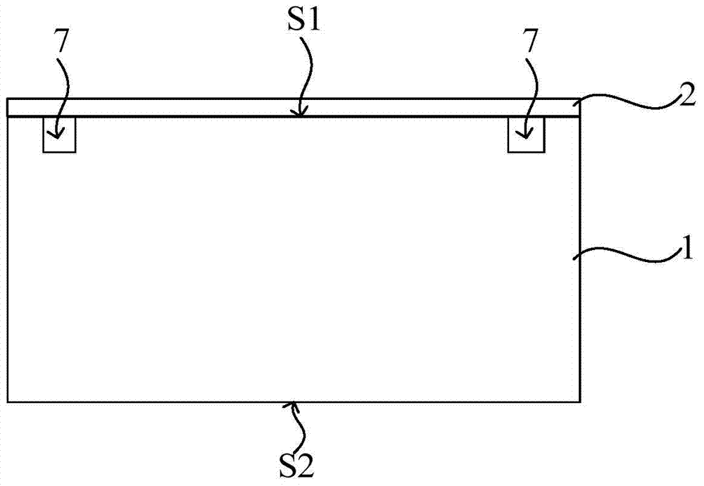
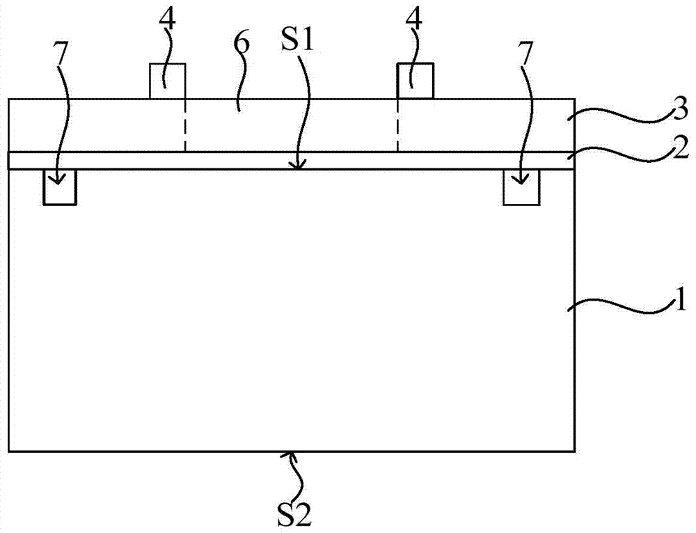
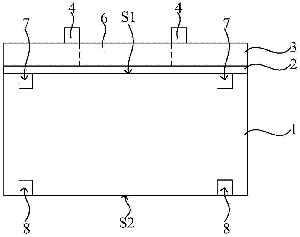
[0062] refer to Figure 5 , provide a wafer 100, the wafer has a front side S1 and a back side S2, the front side S1 and the back side S2 are parallel to each other.
[0063] In a specific embodiment, an alignment mark (not shown in the figure) may be formed on the front surface S1 of the wafer 100 , and the alignment mark plays an alignment role in the subsequent photolithography process for defining the position of the device pattern.
[0064] In a specific embodiment, the wafer 100 may be a silicon wafer, a germanium wafer, or a silicon-on-insulator wafer, etc.; or the material of the wafer 100 may also include other materials, such as III-V compounds such as gallium arsenide. Those skilled in the art can select wafers according to needs, so the type of wafers should not limit the protection scope of the present invention.
[0065] refer to Figure 6 , an insulating layer 101 is formed on the front surface S1 of the wafer 100, and the insulating layer 101 plays an insulat...
no. 2 example
[0103] In this example, refer to Figure 13 , Figure 14 , Figure 14 for correspondence Figure 13 top view of Figure 13 for correspondence Figure 14 The schematic diagram of the cross-sectional structure in the BB direction of , the detection mark 302 includes two sets of scale lines opposite to each other, which are the first set of scale lines 311 and the second set of scale lines 312 . The first set of scale lines 311 includes multiple first scale lines 321 spaced apart from each other on a straight line of the cross, and the second set of scale lines 312 includes multiple second scale lines spaced apart from each other on another straight line of the cross. 322;
[0104] The intersection point of the cross is defined within the boundary range of the lower surface of the device figure, the lower surface boundary of the device figure has two first intersection points on the first set of scale lines 311, and two second intersection points on the second set of scale l...
no. 3 example
[0121] refer to Figure 18 , Figure 18As a top view, detection marks 502 are formed on the insulating layer 501 . The detection mark 502 includes a cross first coordinate axis 511 and a second coordinate axis 512, and the intersection of the first coordinate axis 511 and the second coordinate axis 512 is defined in the lower surface of the device pattern to be formed;
[0122] A plurality of first scale lines 521 distributed at equal intervals are arranged on the first coordinate axis 511 , and a plurality of second scale lines 522 distributed at equal intervals are arranged on the second coordinate axis 512 . The predefined first alignment position is the first coordinate of the two first intersection points of the boundary of the lower surface of the subsequent device pattern and the first coordinate axis 511, and the second point of the two second intersection points of the boundary of the lower surface of the device pattern and the second coordinate axis 512. coordinate...
PUM
 Abstract
Description
Claims
Application Information
 - R&D
- Intellectual Property
- Life Sciences
- Materials
- Tech Scout
- Unparalleled Data Quality
- Higher Quality Content
- 60% Fewer Hallucinations
Browse by: Latest US Patents, China's latest patents, Technical Efficacy Thesaurus, Application Domain, Technology Topic, Popular Technical Reports.
© 2025 PatSnap. All rights reserved.Legal|Privacy policy|Modern Slavery Act Transparency Statement|Sitemap|About US| Contact US: help@patsnap.com


