
Water spraying propulsion pump structure capable of measuring dynamic exciting force of blade

A technology of dynamic excitation force and water jet propulsion, which is applied in the direction of measuring force, measuring devices, pumps, etc., can solve problems affecting measurement accuracy and measurement errors, and achieve the goal of improving economic benefits, increasing service life, and good anti-interference ability Effect

Active Publication Date: 2015-05-27
JIANGSU UNIV
View PDF8 Cites 7 Cited by
  • Summary
  • Abstract
  • Description
  • Claims
  • Application Information

AI Technical Summary

Problems solved by technology

However, this patent only measures the axial force, and does not measure the torque and radial force torque, but the whole device has only one rotating shaft, and when the external force drives the shaft to rotate, there will be additional additional force acting on the shaft, making the measurement error
Publication No. CN104034465A discloses the force-measuring mechanism in the device for measuring the rotating moment of a pitch-adjustable blade. This patent uses a cantilever strain beam placed horizontally along the center of the hub to measure the rotating blade moment. However, the force-measuring mechanism It is not directly connected to the measured blade, so the force and moment on the rotor blade cannot be directly transmitted to the force measuring mechanism, which affects the measurement accuracy

Method used


Image

  • Water spraying propulsion pump structure capable of measuring dynamic exciting force of blade
  • Water spraying propulsion pump structure capable of measuring dynamic exciting force of blade
  • Water spraying propulsion pump structure capable of measuring dynamic exciting force of blade

Examples


Embodiment Construction

[0018] The technical solution of the present invention will be described in detail below in conjunction with the accompanying drawings.

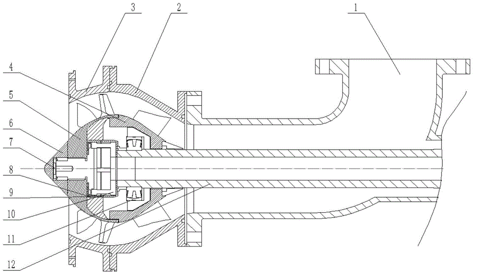
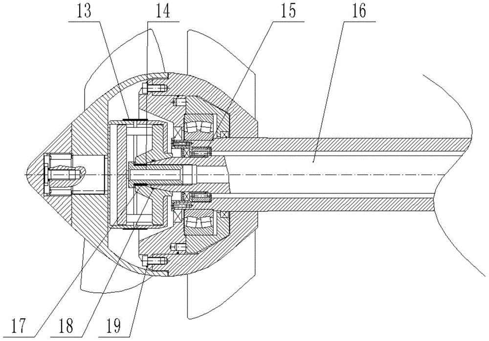
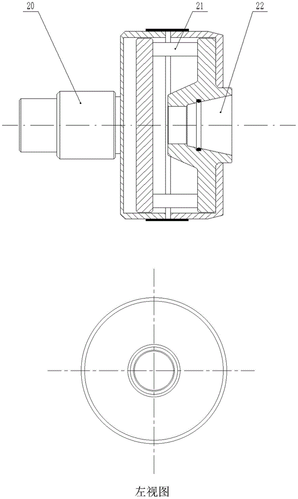
[0019] Such as figure 1 As shown, the tapered hole 22 of the dynamometer is consistent with the taper of the inner shaft 16 to form an interference fit, sealed with a sealing ring 18, and fastened with a fastening screw 14 to connect.

[0020] Such as figure 2 As shown, the cylindrical outer shaft 20 of the outer cover of the dynamometer cooperates with the hub of the impeller 5, and is fastened and connected with the screw 7. The pulley drives the outer shaft 12 to rotate, and through the transmission of two pairs of bearings 11 and 15, it drives and is fixedly connected with the inner shaft 16. The dynamometer 10 and the impeller 5 rotate, which avoids the external force interference generated by the general motor directly connected to the shaft to the rotating parts, and can ensure the accuracy and reliability of the dynamic excitation ...


PUM


Abstract

The invention relates to a water spraying propulsion pump structure capable of measuring the dynamic exciting force of a blade. A cone-shaped through hole of a force measuring machine is consistent with the taper of an inner shaft of the pump, and the through hole and the inner shaft of the pump are connected through a tightening screw in a fastening manner; a cylinder outer shaft of an outer hood I of the force measuring machine is tightly connected with an inner hole of a hub of an impeller through a bolt; twenty-four strain pieces are stuck on four deflection square columns of the force measuring machine so as to form six full-bridge Wheatstone bridges; bearings are fixed on the outer shaft, the outer shaft and the inner shaft are connected through the bearings, the outer shaft is driven by a belt wheel to rotate, and the impeller and the force measuring machine also rotate synchronously. In the rotating process, the four deflection square columns of the force measuring machine are subjected to deformations such as bending and torsion, the twenty-four strain pieces stuck on the square columns are also subjected to the same deformations, and a needed physical quantity can be obtained by using corresponding software.

Description

technical field [0001] The invention relates to a mixed-flow pump used for dynamic excitation force measurement and a force measurement method thereof, and is mainly used for measuring the dynamic excitation force of a propulsion pump impeller in a water jet propulsion structure. Background technique [0002] The strain gauge dynamometer is a bridge circuit (such as a Wheatstone bridge) composed of one or more elastic bodies that can deform after being stressed, and a resistance strain gauge that can sense the deformation, and can connect the resistance The strain gauge is fixedly pasted on the elastic body and is a load cell composed of three parts: an adhesive that can conduct strain and a sealant that protects the electronic circuit. After being subjected to an external force, the deformation of the strain gauge pasted on the elastic body will cause a change in resistance, so that the composed Wheatstone bridge loses balance and outputs an electrical signal that changes l...

Claims


Application Information

Patent Timeline
Patent Type & Authority Applications(China)
IPC IPC(8): G01L1/22F04D13/02
Inventor 张德胜张琳施卫东张俊杰冯琦
Owner JIANGSU UNIV
Learn More