
Automatic antenna pattern testing system

An automatic test system and antenna pattern technology, which is applied in the antenna radiation pattern and other directions, can solve the problems of antenna test system requirements, long research and development cycle, and small market scope, and achieve easy promotion and use, good intelligence, and high intuitiveness Effect

Inactive Publication Date: 2015-05-27
XIAN HUAYONG ELECTROMECHANICAL SCI & TECH
View PDF0 Cites 3 Cited by
  • Summary
  • Abstract
  • Description
  • Claims
  • Application Information

AI Technical Summary

Problems solved by technology

[0003] Early antenna testing mainly relied on manual work, with large errors and low efficiency. With the development of computer science and technology, an automatic control system for antenna testing has emerged. Practice and small-scale antenna engineering tests require antenna test systems, and the cost is high and the development cycle is long, so its market scope is small

Method used


Image

  • Automatic antenna pattern testing system

Examples


Embodiment Construction

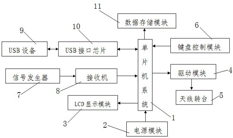
[0023] Such as figure 1 As shown, the present invention includes a single-chip microcomputer system 1 and a power supply module 2 connected with the single-chip microcomputer system 1 for supplying power to the system. The input end of the single-chip microcomputer system 1 is connected with a keyboard control module 6 and a receiver 8. The output end of the LCD display module 3 and the data storage module 11 are connected, the single-chip microcomputer system 1 is also connected with the antenna turntable 5 through the drive module 4, the receiver 8 is connected with the signal generator 7, and the USB device 9 is connected through the USB interface chip 10 is connected with the single-chip microcomputer system 1.

[0024] In this embodiment, the single-chip microcomputer system 1 is an MSP430 single-chip microcomputer.

[0025] In this embodiment, the LCD display module 3 is a 12864 LCD display with a Chinese character library.

[0026] In this embodiment, the drive module...


PUM


Abstract

The invention discloses an automatic antenna pattern testing system, which comprises a single chip microcomputer system and a power supply module connected with the single chip microcomputer system for providing power for the system, wherein the input end of the single chip microcomputer system is connected with a keyboard control module and a receiver; the output end of the single chip microcomputer system is connected with an LCD display module and a data storage module; the single chip microcomputer system is also connected with an antenna turntable via a driving module; the receiver is connected with a signal generator; and USB equipment is connected with the single chip microcomputer system via a USB interface chip. According to the automatic antenna pattern testing system, a manual testing function is provided; movement of the turntable, acquisition, display and storage of antenna signals and drawing of the pattern can be controlled through external input signals; the system is stable; functions are comprehensive; control is convenient; the cost is saved; the measurement precision is high; and popularization and use are facilitated.

Description

technical field [0001] The invention belongs to the technical field of antennas, and in particular relates to an automatic test system for antenna pattern. Background technique [0002] The so-called antenna pattern refers to the graph of the relative field strength (normalized modulus) of the radiation field changing with the direction at a certain distance from the antenna. Usually, two mutually perpendicular plane patterns in the maximum radiation direction of the antenna are used. To indicate that the antenna pattern is an important graph to measure the performance of the antenna, and various parameters of the antenna can be observed from the antenna pattern. [0003] Early antenna testing mainly relied on manual work, with large errors and low efficiency. With the development of computer science and technology, an automatic control system for antenna testing has emerged. Practice and small-scale antenna engineering tests require antenna test systems, and the cost is hi...

Claims


Application Information

Patent Timeline
IPC IPC(8): G01R29/10
Inventor 康培健
Owner XIAN HUAYONG ELECTROMECHANICAL SCI & TECH
Learn More