Narrow-band difference band-pass filter based on terminal short circuit self-coupling annular resonator

A technology of ring resonators and bandpass filters, applied in resonators, circuits, waveguide devices, etc., can solve the problem of difficult differential filter applications with balanced circuits, unsatisfactory out-of-band common-mode signal suppression, and no research and Report and other issues, to achieve high common mode rejection, small insertion loss, easy to achieve the effect

Inactive Publication Date: 2015-05-27
NANJING UNIV OF SCI & TECH
View PDF6 Cites 3 Cited by
  • Summary
  • Abstract
  • Description
  • Claims
  • Application Information

AI Technical Summary

Problems solved by technology

In recent years, some scholars have first proposed a multi-stage broadband coupling differential bandpass filter structure, but this structure is difficult to apply to balanced circuits as a real differential filter due to the lack of suppression of common-mode signals.
In order to overcome this shortcoming, an ultra-wideband microstrip differential bandpass filter with good common-mode rejection characteristics is designed and applied, but in order to meet the requirements of the ultra-wideband frequency band, but because it is connected in multiple stages, the entire circuit is enlarged bulk; and rejection of out-of-band common-mode signals is not ideal
In order to reduce the volume, some scholars have used coupled resonators and coupled lines to improve common-mode rejection and extend the upper limit stopband of differential mode, but its differential loss is relatively large
Based on the above analysis, we proposed a narrow-band differential bandpass filter based on short-circuited self-coupling ring resonators, and no related research and reports have been found.

Method used


Image

  • Narrow-band difference band-pass filter based on terminal short circuit self-coupling annular resonator
  • Narrow-band difference band-pass filter based on terminal short circuit self-coupling annular resonator
  • Narrow-band difference band-pass filter based on terminal short circuit self-coupling annular resonator

Examples


Embodiment Construction

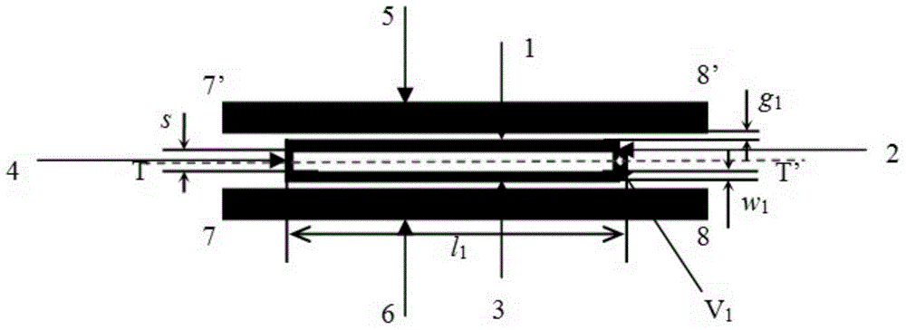
[0015] The invention discloses a narrow-band differential bandpass filter based on a terminal short-circuit self-coupling ring resonator, which includes a terminal short-circuit self-coupling ring resonator, the terminal short-circuit self-coupling ring resonator is rectangular, and the four microstrip lines are clockwise The directions are the first microstrip line 1, the second microstrip line 2, the third microstrip line 3, and the fourth microstrip line 4. The first microstrip line 1 is the upper side of the rectangle, and the first microstrip line 1 and the The third microstrip line 3 is symmetrical up and down, the second microstrip line 2 and the fourth microstrip line 4 are symmetrical left and right, and the right end of the second microstrip line 2 is provided with a first metallized through hole V 1 , the first microstrip line 1 is coupled with the fifth microstrip line 5, the third microstrip line 3 is coupled with the sixth microstrip line 6, one port of the sixth ...


PUM


Abstract

The invention discloses a narrow-band difference band-pass filter based on a terminal short circuit self-coupling annular resonator. The narrow-band difference band-pass filter comprises a terminal short circuit self-coupling annular resonator and two coupling micro band lines. Micro band line design with distribution parameters is adopted. The narrow-band difference band-pass filter has the advantages of light weight, high reliability, excellent property, good temperature stability, large-scale production, low cost, and the like, is wide in application prospect in radar of different frequency bands, communication and future high-velocity data wireless communication, and can be particularly used in corresponding systems with harsh requirements on weight, property and reliability.

Description

technical field [0001] The invention belongs to the field of microwave and millimeter wave technology, in particular to a narrow-band differential band-pass filter based on a terminal short-circuit self-coupling ring resonator. Background technique [0002] With the rapid development of modern wireless communication systems, the needs and applications of balanced circuits are becoming more and more important. The differential filter is particularly important in the balanced circuit structure because of its good anti-noise interference and dynamic range characteristics. For a better differential filter structure, only the desired differential-mode signal passes through the filter structure, while common-mode signals are rejected. In addition, the differential filter must have good edge selection characteristics and harmonic suppression characteristics. In recent years, many different kinds of differential filter structures have been proposed to meet the needs of narrowband,...

Claims


Application Information

Patent Timeline
Patent Type & Authority Applications(China)
IPC IPC(8): H01P1/203H01P7/08
Inventor 康炜沈义进王辉吴文
Owner NANJING UNIV OF SCI & TECH
Why Eureka
Try Eureka