
Constant-current driving circuit for LED switch

A technology of constant current drive and LED module, which is applied in the direction of electric lamp circuit layout, electric light source, lighting device, etc. It can solve the problems of affecting the service life of lamps, low efficiency of LED constant current drive circuit, and complicated application design, so as to save electrolysis Capacitance, simple application design, and high efficiency

Inactive Publication Date: 2015-05-27
SHANGHAI LATRONIX TECH CORP
View PDF7 Cites 21 Cited by
  • Summary
  • Abstract
  • Description
  • Claims
  • Application Information

AI Technical Summary

Problems solved by technology

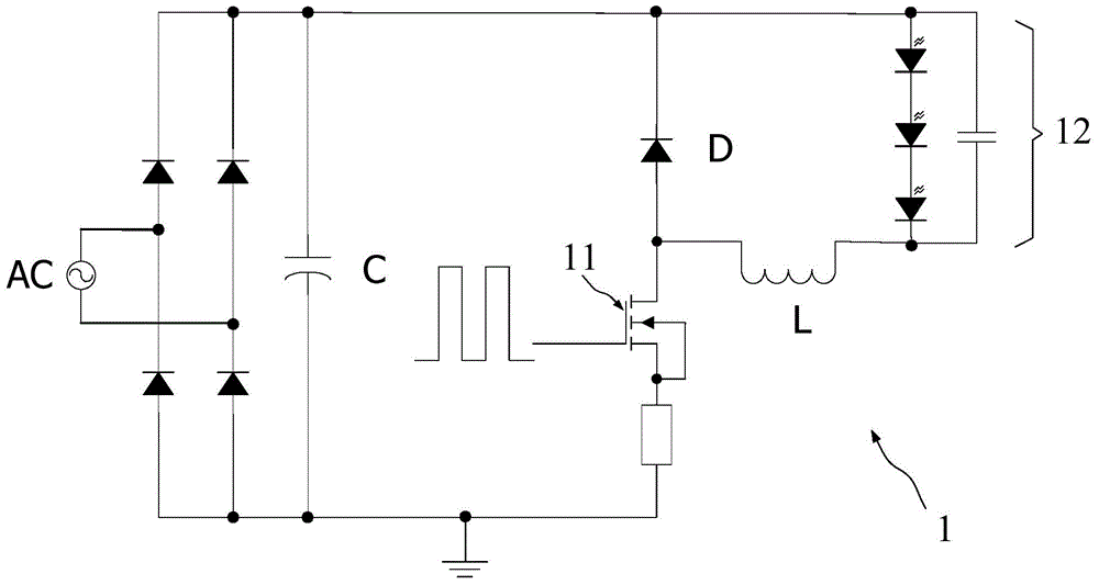
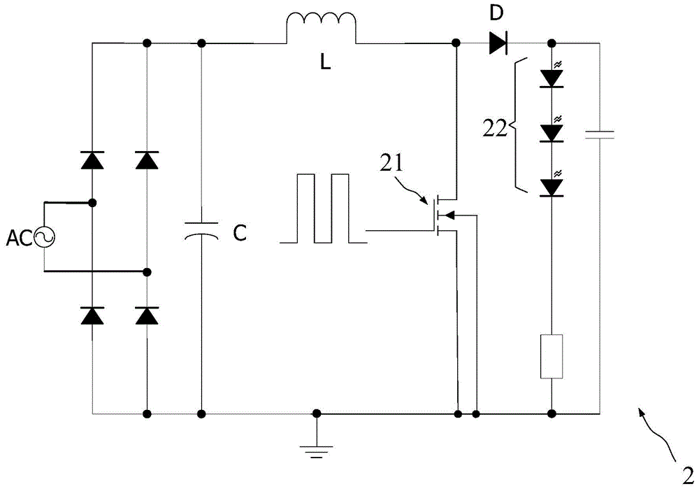
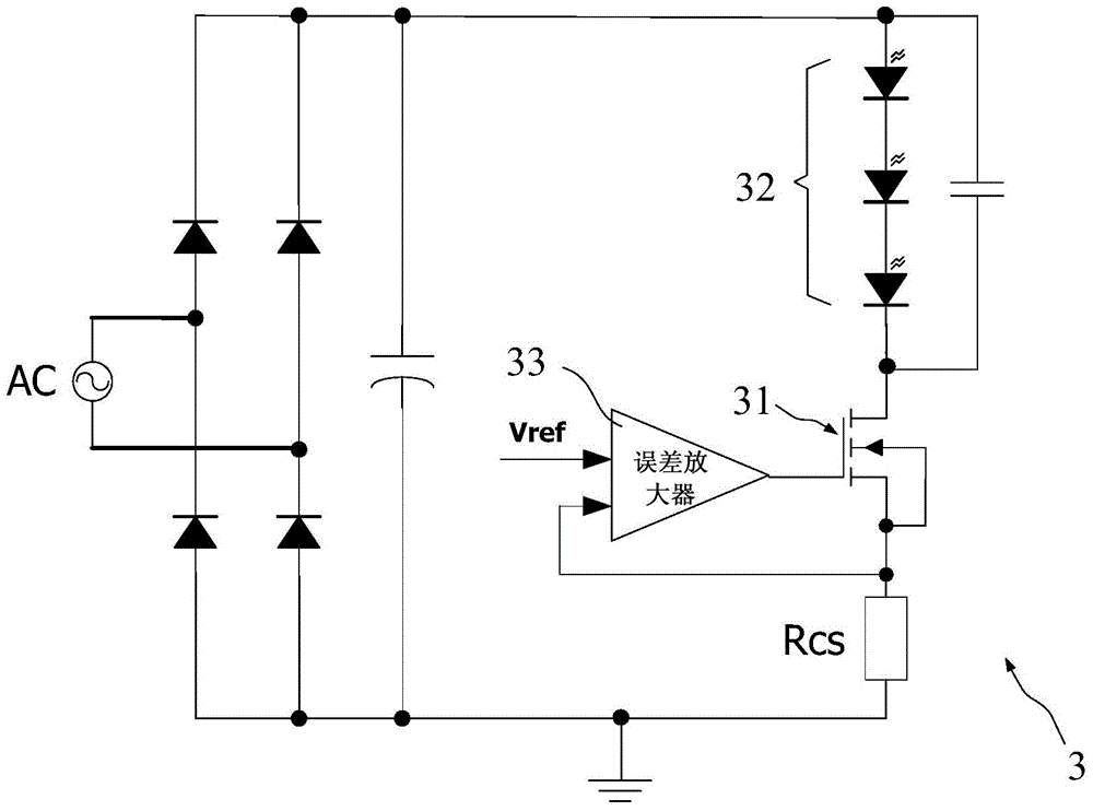
[0007] In view of the above-mentioned shortcomings of the prior art, the purpose of the present invention is to provide a LED switch constant current drive circuit, which is used to solve the problem that the LED constant current drive circuit of the Buck and Boost switch topologies in the prior art needs to use inductors, capacitors, etc. Energy storage device, the application design is relatively complicated, which affects the service life of the lamp; the efficiency of the linearly controlled LED constant current drive circuit is low, etc.

Method used


Image

  • Constant-current driving circuit for LED switch
  • Constant-current driving circuit for LED switch
  • Constant-current driving circuit for LED switch

Examples


Embodiment Construction

[0059] Embodiments of the present invention are described below through specific examples, and those skilled in the art can easily understand other advantages and effects of the present invention from the content disclosed in this specification. The present invention can also be implemented or applied through other different specific implementation modes, and various modifications or changes can be made to the details in this specification based on different viewpoints and applications without departing from the spirit of the present invention.

[0060] see Figure 4 to Figure 9 . It should be noted that the diagrams provided in this embodiment are only schematically illustrating the basic idea of ​​the present invention, and only the components related to the present invention are shown in the diagrams rather than the number, shape and shape of the components in actual implementation. Dimensional drawing, the type, quantity and proportion of each component can be changed arb...


PUM


Abstract

The invention provides a constant-current driving circuit for an LED switch. The constant-current driving circuit for the LED switch at least comprises a voltage input module, an LED module, a power tube, a filter, an error amplifier, a pulse width modulation circuit, a current limiting circuit, a control circuit and a driving circuit, wherein the LED module is connected with the voltage input module; the power tube is connected with the LED module; constant current can be achieved by adjusting the duty cycle of the power tube; the filter is connected with the output end of the power tube and is used for filtering sampling voltage; the error amplifier is used for comparing the sampling voltage with reference voltage; the pulse width modulation circuit is used for generating a PWM signal; the current limiting circuit is used for adjusting the amplitude of the PWM signal; the control circuit and the driving circuit are used for adjusting and driving the gate voltage of the power tube. According to the constant-current circuit for the LED switch, the constant current of the LED can be achieved by adopting a switching topology and linear topology combined novel topology structure, no inductor or electrolytic capacitor is needed, the power tube is controlled in a switch mode, and the efficiency is higher than that of a pure linear control structure.

Description

technical field [0001] The invention relates to the technical field of LED drive control, in particular to an LED switch constant current drive circuit. Background technique [0002] LEDs have been widely used in indicator lights, displays and lighting fields due to their advantages over traditional light sources such as high efficiency, long life, unbreakable, high switching speed, and high reliability. [0003] LED is a semiconductor device that works under low voltage DC conditions. For lighting applications, the external voltage needs to be greater than the forward drive voltage VF value of the LED. At the same time, a constant current control circuit is required to make the LED diode work under constant current conditions to meet the lighting application requirements. When the input voltage is higher than the VF of the LED, the so-called Buck step-down circuit is generally used to reduce the voltage to be consistent with VF to make it work; on the contrary, when the in...

Claims


Application Information

Patent Timeline
Patent Type & Authority Applications(China)
IPC IPC(8): H05B37/02
Inventor 严守平蔡晓辉
Owner SHANGHAI LATRONIX TECH CORP
Learn More