An industrial waste gas purification device

A purification device and industrial waste gas technology, applied in the field of air purification, can solve the problems of inability to completely purify waste gas impurities, waste gas impurities, living environment damage, etc., achieve a wide range of use, easy replacement and installation, and improve purification effect of effect

Active Publication Date: 2016-05-18
青岛华茂环保科技有限公司
View PDF3 Cites 0 Cited by
  • Summary
  • Abstract
  • Description
  • Claims
  • Application Information

AI Technical Summary

Problems solved by technology

[0002] At present, industrial waste gas is a major source of pollution. Various toxic and harmful gases contained in industrial waste gas have caused great pollution to the environment, such as sulfur dioxide and hydrogen sulfide, and some particulate matter has caused serious air pollution to the public environment. And as one of the main sources of air pollution, industrial waste gas has a great destructive effect on the living environment of human beings. Therefore, it is very important to effectively treat industrial waste gas so that it can meet the appropriate emission requirements before entering the atmospheric environment. Important practical significance, the Chinese patent document CN201420293216.7 discloses an industrial waste gas purifier, which is composed of an air inlet pipe, an air outlet pipe and a spray head. The impurities in the exhaust gas are settled by the spray head, and then the gas passes through the second filter body and the third filter body to purify the exhaust gas. However, this structural design is relatively simple and cannot completely purify the impurities contained in the exhaust gas. After filtering, the exhaust gas still contains impurities. It has not been removed, which not only reduces the work efficiency, but also cannot completely purify the impurities contained in the exhaust gas.

Method used


Image

  • An industrial waste gas purification device

Examples


Embodiment Construction

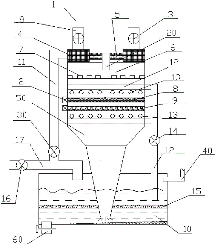
[0025] Such as figure 1 As shown, the first specific embodiment of the present invention is: an industrial exhaust gas purification device, which includes a body 1 and a water storage tank 10. The water storage tank 10 is a closed cavity and is arranged below the body 1. The water storage tank 10 is filled with filtered water, and the liquid level in the storage tank 10 is 2 / 3 to 5 / 6 of the total height of the inner cavity of the storage tank. In this embodiment, the liquid level is preferably 2 / 3. A funnel 50 is arranged at the bottom of the body 1, and the lower end of the funnel 50 passes through the closed upper wall of the water storage tank 10 and is inserted under the liquid level in the water storage tank 10. The waste gas is introduced into the water storage tank 10, and the liquid level in the water storage tank 10 exceeds the mouth of the funnel 50 and the mouth of the funnel 50 is completely submerged under the liquid surface, so that the waste gas discharged from ...


PUM


Abstract

The invention discloses an industrial waste gas purifying device, which comprises a body and a water reservoir, wherein an air inlet is arranged above the body; an air inlet valve is arranged on the air inlet; a filter chamber is connected to the lower part of the air inlet; the filter chamber is connected with an air inlet pipe through a main pipe, and multiple air holes are formed in the surface of the air inlet pipe, and an oil filter board is arranged in the body; a filter layer is arranged below the oil filter board, the water reservoir is a closed cavity and is arranged blow the body, filtered water is contained in the water reservoir, a funnel is arranged on the lower part of the body, the lower end of the funnel penetrates through the top wall of the water reservoir and is inserted into the liquid in the water reservoir, an air outlet pipe is arranged on the lower part of the body, an air outlet valve is arranged on the air outlet pipe, the pipe orifice of the air outlet pipe penetrates through one side of the top wall of the water reservoir and is inserted into the cavity on the upper part of the water reservoir, the pipe orifice of the air outlet pipe which is inserted into the water reservoir is higher than the liquid level in the water reservoir, and the industrial waste gas purifying device has the advantages of reasonable structural design, good purifying effect and long service life.

Description

technical field [0001] The invention relates to the field of air purification, in particular to an industrial waste gas purification device. Background technique [0002] At present, industrial waste gas is a major source of pollution. Various toxic and harmful gases contained in industrial waste gas have caused great pollution to the environment, such as sulfur dioxide and hydrogen sulfide, and some particulate matter has caused serious air pollution to the public environment. And as one of the main sources of air pollution, industrial waste gas has a great destructive effect on the living environment of human beings. Therefore, it is very important to effectively treat industrial waste gas so that it can meet the appropriate emission requirements before entering the atmospheric environment. Important practical significance, the Chinese patent document CN201420293216.7 discloses an industrial waste gas purifier, which is composed of an air inlet pipe, an air outlet pipe and...

Claims


Application Information

Patent Timeline
Patent Type & Authority Patents(China)
IPC IPC(8): B01D50/00B01D53/78
Inventor 徐鸿
Owner 青岛华茂环保科技有限公司
Why Eureka
Try Eureka