
Negative-pressure coating method

A technology of negative pressure and coating surface, applied in chemical instruments and methods, membrane technology, semi-permeable membrane separation, etc., can solve problems such as low efficiency, uneven film thickness, repeated spraying, etc., and achieve improved stability and improved efficiency , Improve the effect of forming quality

Inactive Publication Date: 2015-06-03
CHENGDU INTERMENT TECH
View PDF5 Cites 1 Cited by
  • Summary
  • Abstract
  • Description
  • Claims
  • Application Information

AI Technical Summary

Problems solved by technology

The efficiency of manual painting is low, and the thickness of the film layer is uneven. The main reasons include: 1. The amount of film liquid sprayed by the spray gun is not uniform; 2. The moving speed of the spray gun is not uniform. The larger the amount, the greater the thickness of the spraying, and the moving speed of the spray gun is controlled manually, which cannot guarantee that the spraying amount at each position is consistent; 3. It is difficult to control the number of repeated spraying
When spraying manually, it is generally necessary to repeat the spraying on the spraying object several times. In this process, it is impossible to guarantee that each part is sprayed the same number of times. For example, when spraying a certain part, other sprayed parts around it may also be sprayed.
Although the efficiency of mechanical spraying with tools is high, there are still problems such as uneven spraying of film liquid and repeated spraying, and the thickness of the film layer is still difficult to control.

Method used


Image

  • Negative-pressure coating method
  • Negative-pressure coating method

Examples


Embodiment 1

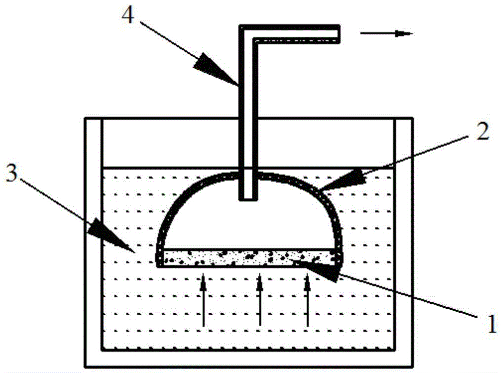
[0023] Such as figure 1 The shown negative pressure coating method of the present invention has a tooling 2 comprising a porous plate-shaped membrane support body 1, the coating surface of the membrane layer support body 1 faces an open space, and the non-coated surface of the membrane layer support body 1 is located in the negative pressure space Among them, the negative pressure space communicates with negative pressure equipment such as a vacuum pump through a pipeline 4 . According to the filtration requirements of the membrane layer, the slurry 3 is configured in a conventional manner. The powder particles in the slurry 3 are spherical, which can better ensure the permeability of the membrane layer and the uniformity of the pore size. At the same time, the particle size of the powder particles in the slurry 3 is about half of the pore diameter on the membrane support 1, and the powder particles of this ratio are more likely to accumulate and block in the pores of the memb...

Embodiment 2

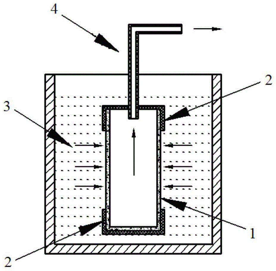
[0026] On the basis of Example 1, the porous tubular membrane layer support 1 is coated. The two ends of the tubular film layer support body 1 are covered with the tooling 2 of the rubber sealing sleeve structure to make it sealed. Then, a through hole is opened on the sealing sleeve at one end to connect the pipeline 4 to the negative pressure equipment, and the inner cavity of the tubular membrane support body 1 is used as a negative pressure space. Place the tooling 2 and the film layer support 1 in the slurry 3 as a whole, open the negative pressure device and pass the pipeline 4 to make the air pressure in the inner cavity of the tubular film support 1 less than the pressure in the slurry 3, and the pressure in the slurry 3 The powder particles uniformly adhere to the outer coating surface of the film layer support 1 under the action of the pressure difference to form a film layer. Finally, the dried and formed membrane layer support body 1 having the membrane layer is s...


PUM


Abstract

The invention relates to a negative-pressure coating method comprising the steps of a. providing a tool with a coating supporting body, enabling the coated surface of the coating supporting body to face to an open space, and locating the non-coated surface of the coating supporting body in a negative-pressure space communicated with negative-pressure equipment such as a vacuum pump; b. at least arranging the whole coated surface of the coating supporting body in the tool into slurry, and isolating the non-coated surface of the coating supporting body from the slurry; c. enabling the air pressure inside the negative-pressure space to be lower than the pressure in the slurry through the negative-pressure equipment, and attaching powder particles in the slurry onto the coated surface of the coating supporting body under the action of a pressure difference to form a coating; and d. sintering the dry formed coating supporting body with the coating to form a porous film. The negative-pressure coating method disclosed by the invention is very simple and feasible, the efficiency of uniformly and rapidly coating the coating supporting body is greatly increased, meanwhile, the forming quality of the coating is also remarkably improved, and the stability of the filtering effect of the porous metal film is greatly improved.

Description

technical field [0001] The invention relates to a film coating method, in particular to a negative pressure film coating method. Background technique [0002] In many industries including high-temperature filtration, it is necessary to filter gases through filter membranes. A common structure of filter membranes is metal membranes, the base material of which is metal, and the membrane material is metal or metal oxide, and is used for separation Porous membranes for gases and impurities in gases, where the membrane material is composed of powder particles. The separation process is to use the gaps between the powder particles of the membrane material to separate the gas and impurities. The size of the gaps between the powder particles is generally hundreds of nanometers. [0003] According to the cross-sectional structure of the porous metal membrane, it is further divided into a symmetrical porous metal membrane and an asymmetric porous metal membrane. As the thickness of ...

Claims


Application Information

Patent Timeline
IPC IPC(8): B01D67/00
Inventor 高麟汪涛李波彭国林
Owner CHENGDU INTERMENT TECH
Learn More