
Fixing structure for exhaust pipes

A fixed structure and exhaust pipe technology, which is applied in the direction of power unit gas intake, power unit, transportation and packaging, etc., can solve the problems of high risk of rust, easy cracking of solder joints, high cost, etc., to avoid resonance and vibration , Guarantee anti-rust performance, improve the effect of dynamic stiffness

Active Publication Date: 2015-06-03
SAIC-GM-WULING AUTOMOBILE CO LTD
View PDF8 Cites 3 Cited by
  • Summary
  • Abstract
  • Description
  • Claims
  • Application Information

AI Technical Summary

Problems solved by technology

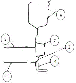
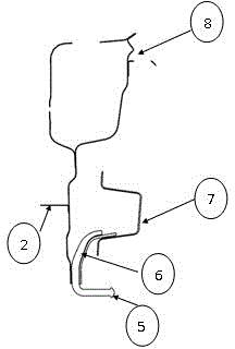
[0003] The main disadvantages of the prior art are: 1. The fixed points of the exhaust pipe are generally designed symmetrically, and it is more common to arrange them symmetrically on the rear longitudinal beam 4 and the rear floor 2
The rigidity on the rear longitudinal beam 4 is easy to ensure, but the rigidity on the rear floor 2 is relatively poor, because the material thickness of the rear floor 2 is thin, and the shaking of the exhaust pipe during the driving of the vehicle is likely to cause resonance and vibration of the rear floor 2; 2. The exhaust pipe The structural strength is poor, and the solder joints are easy to crack; 3. In order to improve the rigidity of the mounting point on the rear floor 2, the thickness of the exhaust pipe mounting bracket 3 will be selected to be a relatively large structure, which is heavy and expensive; 4. The rear floor 2. The closed cavity structure of the fixed point of the exhaust pipe cannot ensure sufficient electrophoresis in the cavity, and the electrophoretic fluid will remain in the cavity, and there is a high risk of rusting directly in contact with moisture outside the vehicle at the bottom of the vehicle

Method used


Image

  • Fixing structure for exhaust pipes
  • Fixing structure for exhaust pipes
  • Fixing structure for exhaust pipes

Examples


Embodiment Construction

[0027] The present invention will be further described below in conjunction with the accompanying drawings and specific embodiments.

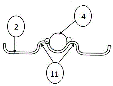
[0028] Figure 3 to Figure 12 The reference numerals in are: rear longitudinal beam 1; rear floor 2; first exhaust pipe installation bracket 3; first exhaust pipe installation hook 4; second exhaust pipe installation hook 5; second exhaust pipe Mounting bracket 6 ; rear anti-collision beam 7 ; rear end plate 8 ; second-layer plate welding spot 9 ; third-layer plate welding spot 10 ; first reinforcing rib 11 ; second reinforcing rib 12 .

[0029] Such as Figure 3 to Figure 12 As shown, an exhaust pipe fixing structure includes a rear longitudinal beam 1, a rear floor 2, a first exhaust pipe installation bracket 3, a first exhaust pipe installation hook 4, a second exhaust pipe installation hook 5, The second exhaust pipe mounting bracket 6 and the rear anti-collision beam 7, wherein the rear anti-collision beam 7 is respectively connected wit...


PUM


Abstract

The invention provides a fixing structure for exhaust pipes, comprising a rear longitudinal beam, a rear floor, a first exhaust pipe mounting support, a first exhaust pipe mounting hook, a second exhaust pipe mounting hook, a second exhaust pipe mounting support and a rear anti-collision beam. The rear anti-collision beam is connected with the rear longitudinal beam and the rear floor. The first exhaust pipe mounting support and the second exhaust pipe mounting support are both connected with the rear anti-collision beam. The first exhaust pipe mounting hook is disposed on the first exhaust pipe mounting support. The second exhaust pipe mounting hook is disposed on the second exhaust pipe mounting support. The fixing structure has the advantages that dynamic stiffness of the fixing structure is greatly improved, the problem that shaking of the exhaust pipe easily causes resonance and shaking of the floor during running of a vehicle is avoided, electro-coating is sufficient, and the sufficient electrophoretic paint film ensures rust resistance of the fixing structure.

Description

technical field [0001] The invention relates to an automobile body, in particular to an exhaust pipe fixing structure in the automobile body. Background technique [0002] The installation point structure of the exhaust pipe is one of the important hard point structures of the body-in-white. The quality of its structure directly affects the use and vibration of the exhaust pipe, and the durability and reliability of the fixed point of the exhaust pipe. If the structure is not good, the rigidity of the installation point is insufficient, and the shaking movement of the exhaust pipe in the left, right, up and down directions will cause durable cracking of the fixed points of the body, and even cause the exhaust pipe to fall off after the fixing fails, affecting the normal use of the vehicle. The structure of the traditional car exhaust pipe installation point is as follows Figure 1 to Figure 2 As shown, it includes exhaust pipe installation hook 1, rear floor 2, exhaust pipe ...

Claims


Application Information

Patent Timeline
Patent Type & Authority Applications(China)
IPC IPC(8): B60K13/04
Inventor 覃鹏飞朱合标秦海滨
Owner SAIC-GM-WULING AUTOMOBILE CO LTD
Learn More