Airflow-assisted melt micro-separation centrifugal spinning device and method

A technology of centrifugal spinning and melt differentiation, which is applied in the field of spinning and forming, to achieve the effect of prolonging service life, high mesh surface density and orientation degree, and improving production safety performance

Active Publication Date: 2017-03-22
BEIJING UNIV OF CHEM TECH
View PDF9 Cites 5 Cited by
  • Summary
  • Abstract
  • Description
  • Claims
  • Application Information

AI Technical Summary

Problems solved by technology

Since the spinning process of the present invention does not rely on solvent spinning, there is no nee

Method used


Image

  • Airflow-assisted melt micro-separation centrifugal spinning device and method
  • Airflow-assisted melt micro-separation centrifugal spinning device and method
  • Airflow-assisted melt micro-separation centrifugal spinning device and method

Examples


Embodiment Construction

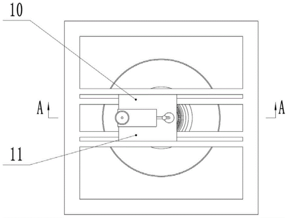
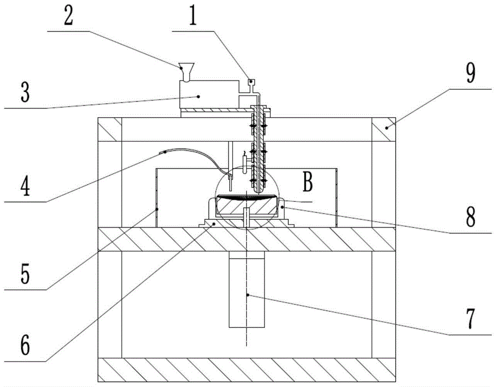
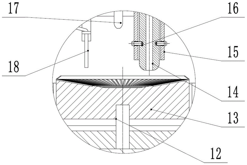
[0017] The present invention proposes an airflow-assisted melt differential centrifugal spinning device, such as Figure 1-3 As shown, it mainly includes: melt metering pump 1, hopper 2, continuous feeding device 3, gas pipe 4, receiving device 5, electromagnetic heating bracket 6, motor 7, electromagnetic heating device 8, spinning box 9, nozzle bracket 10 , slide rail 11, shaft 12, centrifugal differential plate 13, nozzle 14, nozzle heating ring 15, thermocouple 16, infrared thermometer 17 and air pipe support 18, melt metering pump 1, continuous feeding device 3 and nozzle 14 connection , the continuous feeding device 3 and the nozzle 14 are fixed on the nozzle bracket 10 through threaded connection, the nozzle bracket 10 slides on the slide rail 11, the slide rail 11 is welded on the upper part of the box body 9, and the nozzle 14 is at 5 cm above the centrifugal differential plate 12. The eccentric distance from the center line of the centrifugal differential disc 13 is ...


PUM


Abstract

The invention discloses a device and a method for differential centrifugal spinning by using air flow to assist a melt, and belongs to the field of spinning forming. The device comprises a melt metering pump, a material hopper, a continuous material supply device, an air pipe, a receiving device, an electromagnetic heating bracket, a motor, an electromagnetic heating device, a spinning tank body, a spray head bracket, a slide rail, a shaft, a centrifugal differential disc, a spray head, a spray head heating coil, a thermocouple, an infrared temperature measuring instrument, an air pipe bracket and the like, wherein the melt enters the centrifugal differential disc through the eccentric spray head to obtain the initial linear speed, is equalized by a plurality of grooves which are formed in the disc center, enters a comb tooth-shaped structure of the conical surface of the disc edge, is thinned, differentiated and fined under the actions of centrifugal force, high-speed air flow and attaching force of the melt on the conical surface, and is thrown out at high speed, so as to finally form superfine fibers. The device and the method have the advantages that in the fiber preparation process, the efficiency is high, and the green and pollution-free effects are realized; the prepared fiber has higher net surface density and degree of orientation, and the property is excellent; the device is simple, the processing is easy, and the device is suitable for preparing the superfine fibers in a batch way.

Description

technical field [0001] The invention relates to an airflow-assisted melt differential centrifugal spinning device and method, belonging to the field of spinning and forming. Background technique [0002] Melt centrifugal spinning technology is a method in which the polymer melt is thrown out of the pores by the centrifugal force generated by a high-speed rotating device to overcome the surface tension, and the melt is solidified to form fibers. Centrifugal spinning technology started earlier. As early as 1924, there was a patent in the United States that proposed a method of manufacturing fibers in a centrifugal manner; in 1986, European patent EP0168817 pointed out that in centrifugal spinning, the centrifuge acts as a pressure pump, and the melt of the material is pumped. Squeeze through the holes to form fibers; after that, a large number of patents in the United States and Europe have improved the description of the centrifugal spinning method, and the US patent US200800...

Claims


Application Information

Patent Timeline
IPC IPC(8): D01D13/00D01D5/18
CPCD01D5/18D01D13/02
Inventor 杨卫民吴昌政谭晶李好义焦志伟谢鹏程阎华谢同维丁玉梅
Owner BEIJING UNIV OF CHEM TECH
Why Eureka
Try Eureka