
Helical weld pipe line outer diameter measuring device and method based on view detection

A spiral welded pipe and visual inspection technology, applied in the direction of measuring devices, optical devices, instruments, etc., can solve the problems of measurement accuracy position calibration and positioning accuracy, measurement results are greatly affected by human factors, and poor automation, etc., to achieve The calibration process is simple and convenient, avoiding the difficulty of position calibration, and the effect of simple and convenient measurement

Inactive Publication Date: 2015-06-03
SHANDONG UNIV
View PDF4 Cites 30 Cited by
  • Summary
  • Abstract
  • Description
  • Claims
  • Application Information

AI Technical Summary

Problems solved by technology

This measurement method has the following disadvantages: the degree of automation is poor, and the labor intensity is relatively large; the measurement results are greatly affected by human factors; only the average value of the steel pipe diameter can be obtained; the detection frequency is low
However, in the existing measurement methods, the measurement accuracy is greatly affected by the position calibration and positioning accuracy of the sensor.
The utility model with the patent number CN 201488707 describes a device for measuring the diameter of a spiral welded pipeline steel pipe. The inner diameter of the steel pipe is measured by a laser sensor, but the purpose of measuring the outer diameter of the steel pipe cannot be achieved, and the accuracy is easily affected by position calibration and positioning accuracy. Impact

Method used


Image

  • Helical weld pipe line outer diameter measuring device and method based on view detection

Examples


Embodiment Construction

[0036] The specific implementation manner of the present invention will be described below in conjunction with the accompanying drawings.

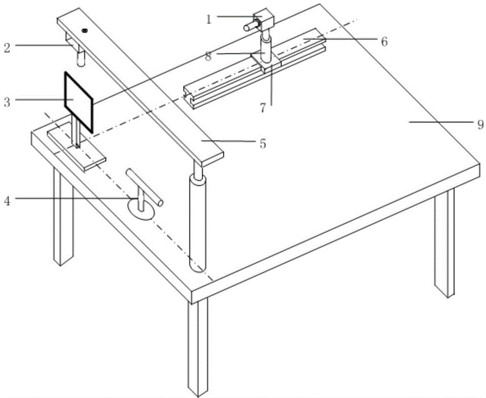
[0037] A device for measuring the outer diameter of a spiral welded pipe line based on visual inspection, including an industrial camera 1, an industrial camera 2, a grid calibration target 3, a line laser generator 4, a cantilever 5, a guide rail 6, a lifting mechanism 8, and a measuring platform 9, and is characterized in that :

[0038]The industrial camera 1, the industrial camera 2, the grid calibration target 3, the line laser generator 4, the cantilever 5, and the guide rail 6 are fixed on the measurement platform 9. The laser plane generated by the line laser generator 4 is perpendicular to the horizontal plane and perpendicular to the direction of the guide rail 6 . The industrial camera 1 is connected with the lifting mechanism 8, and fixed on the slider 7 of the guide rail 6 through the lifting mechanism 8. Its central optical ...


PUM


Abstract

The invention relates to a helical weld pipe line outer diameter measuring device and a helical weld pipe line outer diameter measuring method based on view detection. The helical weld pipe line outer diameter measuring device comprises an industrial camera 1, an industrial camera 2, a grid calibration target, a linear laser generator, a cantilever, a guide track, a lifting mechanism and a measuring platform, wherein the plane of laser generated from the linear laser generator is perpendicular to the horizontal plane; the industrial camera is fixed on the guide track through the lifting mechanism; a central light axis is perpendicular to the plane of the laser; the industrial camera 2 is used for vertically taking images of the edge of a steel pipe and the laser light from top to bottom through the cantilever; the grid calibration target is arranged inside the plane of the laser and perpendicular to the central optical axis of the industrial camera 1; the calibration of the industrial camera is firstly completed; when a helical weld pipe is produced, laser light images are simultaneously taken by the industrial camera 1 and the industrial camera 2, and the outer diameter and the ellipticity of the helical weld pipe can be calculated by processing the images. Due to the cooperation of the double industrial cameras, the guide track and the lifting mechanism, dynamic measurement on the outer diameter and the ellipticity of helical weld pipes of different diameters can be achieved.

Description

technical field [0001] The invention belongs to the technical field of diameter measurement of spiral welded pipes, and relates to a device and method for measuring the outer diameter of spiral welded pipes based on visual detection. Background technique [0002] In the production of steel pipes in the steel industry, along with the trend of "large diameter, thick wall, high steel grade" in domestic and foreign pipeline construction, the production proportion of large diameter spiral welded pipes has been increasing. In the spiral welded pipe production industry, it is required to measure the diameter of the steel pipe during the forming stage to ensure product quality. At present, the pipe diameter measurement method commonly used in factories is to measure manually with a tape measure. This measurement method has the following disadvantages: the degree of automation is poor, and the labor intensity is relatively high; the measurement results are greatly affected by human ...

Claims


Application Information

Patent Timeline
Patent Type & Authority Applications(China)
IPC IPC(8): G01B11/08G01B11/24
Inventor 高进强周长斌李思功马冉
Owner SHANDONG UNIV
Learn More