
Microwave frequency-modulation thermal wave imaging system and microwave frequency-modulation thermal wave imaging method

A thermal wave imaging and microwave technology, used in the fields of non-destructive testing, target detection and medical imaging, which can solve the detection method that relies on thermal images and transient temperature curves, is susceptible to noise interference, and is difficult to overcome heating unevenness and surface emissivity. interference, etc.

Active Publication Date: 2015-06-03
何赟泽
View PDF6 Cites 26 Cited by
  • Summary
  • Abstract
  • Description
  • Claims
  • Application Information

AI Technical Summary

Problems solved by technology

The existing microwave thermal imaging defect detection technology has the following shortcomings: 1) The defect detection method relies on the original thermal image and transient temperature curve, which is susceptible to noise interference; 2) It is difficult to overcome the interference of uneven heating and surface emissivity; 3) The detection time required to obtain information of different depths is long

Method used


Image

  • Microwave frequency-modulation thermal wave imaging system and microwave frequency-modulation thermal wave imaging method
  • Microwave frequency-modulation thermal wave imaging system and microwave frequency-modulation thermal wave imaging method
  • Microwave frequency-modulation thermal wave imaging system and microwave frequency-modulation thermal wave imaging method

Examples


Embodiment Construction

[0056] Specific embodiments of the present invention will be described below in conjunction with the accompanying drawings, so that those skilled in the art can better understand the present invention.

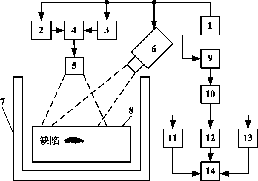
[0057] figure 1 It is a schematic diagram of a microwave frequency modulation thermal wave imaging system, which mainly includes: control module 1, microwave generation device 2, frequency modulation signal generation device 3, amplitude modulation device 4, antenna 5, thermal imager 6, microwave protection device 7, detected Object 8, computer 9, reference signal setting module 10, Fourier transform module-11, time domain cross-correlation module 12, frequency domain cross-correlation module 13, imaging module 14, etc.

[0058] The specific implementation steps of a microwave frequency modulation thermal wave imaging method based on a microwave frequency modulation thermal wave imaging system are as follows:

[0059] 1) Place the inspected object 8 in the microwave protecti...


PUM


Abstract

The invention discloses a microwave frequency-modulation thermal wave imaging system and a microwave frequency-modulation thermal wave imaging method. The microwave frequency-modulation thermal wave imaging method comprises the following steps: heating a detected object by adopting microwaves subjected to amplitude modulation of a frequency-modulation signal, recording the temperature of the surface of the detected object by adopting a thermal imager, setting the frequency-modulation signal or a temperature signal in an area free from defects as a reference signal, carrying out fast Fourier transform on the temperature signal and the reference signal, and extracting the amplitude and the phase position of a special frequency, a peak frequency and the like as characteristic values; carrying out mutual correlation on the temperature signal and the reference signal, and extracting correlation coefficients at a special delay time and a peak delay time as characteristic values; and carrying out frequency domain mutual correlation on the temperature signal and the reference signal, extracting mutual correlation amplitudes and phase positions at the special delay time and the peak delay time as characteristic values, and imaging by adopting the characteristic values of all pixel points in the detected area. The method and the system disclosed by the invention have the advantages of being high in anti-interference performance, abundant in depth information, short in detection time and the like, and can be applied in the fields of non-destructive detection, medical imaging, target detection and the like.

Description

technical field [0001] The invention belongs to the technical fields of non-destructive testing, target detection and medical imaging, and in particular relates to a microwave thermal imaging detection, detection and imaging system and method. Background technique [0002] With the development of modern science and industrial technology, non-destructive testing technology has become a necessary means to ensure product quality and equipment operation safety. At present, representative non-destructive testing technologies mainly include radiographic testing, ultrasonic testing, penetrant testing, magnetic particle testing, eddy current testing, and thermal imaging testing. [0003] Thermal imaging inspection technology uses a heat source to heat the inspected object, and uses a thermal imager to observe and record the temperature change information on the surface of the inspected object, so as to detect and evaluate the surface and internal defects of the inspected object. Th...

Claims


Application Information

Patent Timeline
Patent Type & Authority Applications(China)
IPC IPC(8): G01N25/72G01N25/20
Inventor 何赟泽杨瑞珍
Owner 何赟泽
Learn More