Contact debris flow motion parameter monitoring device and system as well as debris flow early-warning method

A technology for monitoring devices and motion parameters, which is applied in the field of disaster monitoring and debris flow prevention and control engineering, and can solve problems such as complex technical means, difficult application, high false alarm rate, and high false alarm rate

Active Publication Date: 2015-06-03
CHENGDU RUIKEFENG TECH
View PDF9 Cites 14 Cited by
  • Summary
  • Abstract
  • Description
  • Claims
  • Application Information

AI Technical Summary

Problems solved by technology

In the first type of technology, since rainfall is a necessary but not sufficient condition for the formation of debris flow, the critical rainfall threshold of debris flow is less considered to be affected by various factors, so the false alarm rate and false negative rate are extremely high; the second type of technology Among them, because the water content and pore water pressure at different locations in the debris flow basin may be different, the technical means to determine the critical early warning threshold of the debris flow water content or pore water pressure are complex, so it is difficult to apply to engineering practice; in the third category of technology, Since the debris flow occurs during the rainstorm or at night, the debris flow cannot be observed from the video at all, so the practicability of the early warning / forecast method is low; in the fourth type of technology, it is easy to combine the vibration (secondary) signal generated by the debris flow with the outside world The vibration (secondary) signal generated by interference is confused and leads to false alarms, so large-scale promotion and application are relatively limited

Method used


Image

  • Contact debris flow motion parameter monitoring device and system as well as debris flow early-warning method
  • Contact debris flow motion parameter monitoring device and system as well as debris flow early-warning method
  • Contact debris flow motion parameter monitoring device and system as well as debris flow early-warning method

Examples


Embodiment 1

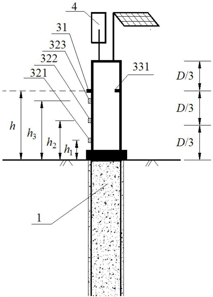
[0068] like Figure 1-1~Figure 1-2 As shown in Fig. 1, a contact-type debris flow movement parameter monitoring device is manufactured, which is used in a disaster prevention and control project of a debris flow channel A.

[0069] According to on-site investigation and investigation, the debris flow formation area, circulation area, and hazard area in the ditch are divided, and the thickness of the loose accumulation body in the ditch is determined to be 10m, and the maximum mud depth in the ditch is D=3m. Channel area 25Km 2, the length of the main groove is 8Km, and the average width of the channel in the circulation area is B=40m.

[0070] Picture 1-1 It is a schematic diagram of the overall structure of the contact debris flow movement parameter monitoring device. The main structure of the contact debris flow movement parameter monitoring device is a columnar monitoring pile 1, and the lower part of the columnar monitoring pile 1 is made of micro-steel pipe piles, spec...

Embodiment 2

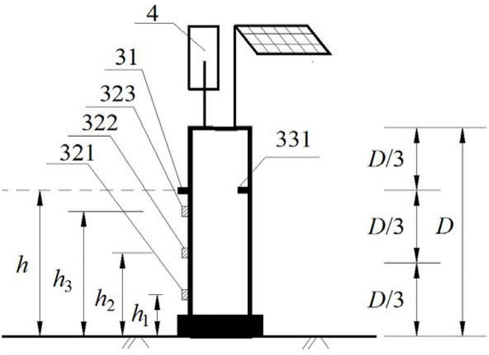
[0079] like Figure 2-1 to Figure 2-4 As shown, based on the contact-type debris flow movement parameter monitoring device processed in Example 1, a contact-type debris flow movement parameter monitoring system is further arranged in the debris flow channel A.

[0080] Figure 2-1 It is a schematic diagram of the structure of the contact debris flow movement parameter monitoring system. The monitoring system includes a contact monitoring device for debris flow movement parameters and an upper control center 5 . The contact debris flow movement parameter monitoring device also includes a signal transmission device 4 connected to the signal acquisition device 2; the signal transmission device 4 communicates with the upper control center 5 through wireless signals.

[0081] Figure 2-2 It is a schematic diagram of the side section of the arrangement of the contact debris flow movement parameter monitoring device. The contact monitoring devices for debris flow movement paramet...

Embodiment 3

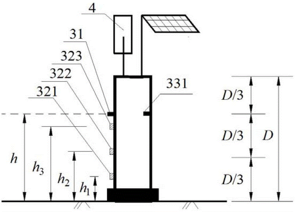
[0084] like Figure 3-1~Figure 3-2 As shown, a contact monitoring system for debris flow movement parameters is arranged in debris flow channel B.

[0085] According to the field investigation and investigation, the debris flow formation area, circulation area, and hazard area in the trench are divided, and the thickness of the loose accumulation body in the trench is determined to be 8m, and the maximum mud depth in the trench is D = 2.7m. Channel area = 50Km 2 , the length of the main channel = 15Km, the average channel width B in the circulation area = 120m.

[0086] The processing contact type debris flow movement parameter monitoring device, which is the same as the first embodiment will not be repeated, the difference is h 1 = 0.4m, h 2 = 1.4m, h 3 =2.4m,

[0087] Figure 3-1 It is a top view schematic diagram of the arrangement of contact debris flow movement parameter monitoring devices, Figure 3-2 Yes Figure 3-1 A-A cross-sectional schematic diagram. Arra...


PUM


Abstract

The invention discloses a contact debris flow motion parameter monitoring device which comprises a columnar monitoring pile, wherein the lower area of the columnar monitoring pile is fixed in a bed of a debris flow gully, and parameter monitoring sensors are arranged in the upper area of the columnar monitoring pile, and comprise an acceleration sensor, an ultrasonic sludge level sensor and an impact force sensor; the ultrasonic sludge level sensor is arranged above the impact force sensor. The invention further provides a contact debris flow motion parameter monitoring system implemented by the monitoring device. An upper control center of the system communicates with a signal transmission device of the monitoring device through a wireless signal, and the contact debris flow motion parameter monitoring device can be arranged in the debris flow gully in a second-stage or third-stage manner. The invention further provides a debris flow multi-stage early-warning method implemented by the monitoring system. By the device and the system, key power parameters during the real-time monitoring of a debris flow motion process can be comprehensively acquired. According to the method, early-warning accuracy can be improved.

Description

technical field [0001] The invention relates to a debris flow monitoring device, system and debris flow early warning method, in particular to a contact type debris flow movement parameter monitoring device, system and debris flow early warning method, belonging to the fields of disaster monitoring and debris flow prevention and control engineering. Background technique [0002] Debris flow is a typical solid-liquid two-phase medium with super flow characteristics and huge destructive ability. It destroys various structures along the way or in the accumulation area through burial and direct impact. It is a typical geological phenomenon in mountainous areas. type of disaster. Debris flow disaster reduction measures can be mainly divided into two categories: engineering measures and monitoring and early warning / forecasting. Monitoring and early warning / forecasting is the most effective measure for debris flow disaster reduction at the present stage because it can effectively r...

Claims


Application Information

Patent Timeline
Patent Type & Authority Applications(China)
IPC IPC(8): G08B21/10
CPCG08B21/10
Inventor 何思明
Owner CHENGDU RUIKEFENG TECH
Why Eureka
Try Eureka