
Mass spectrometer power circuit with adjustable radio frequency

A technology of radio frequency power supply circuit and mass spectrometer, which is applied in the direction of electrical components, output power conversion device, AC power input conversion to DC power output, etc., which can solve the problems of increasing experimental cost, wasting time, cumbersome process, etc., and achieve output signal Effects of stabilization, circuit simplification, and enhanced drive capability

Inactive Publication Date: 2015-06-03
HEFEI INSTITUTES OF PHYSICAL SCIENCE - CHINESE ACAD OF SCI
View PDF5 Cites 7 Cited by
  • Summary
  • Abstract
  • Description
  • Claims
  • Application Information

AI Technical Summary

Problems solved by technology

[0003] At present, most RF power supplies use triggers, inductors and capacitors to oscillate to generate high-frequency signals, and output a single frequency and high-frequency high-voltage power supply with a fixed amplitude.
This kind of RF power supply is used in mass spectrometers, and can only obtain the mass-to-charge ratio of ions under a single condition. If it is necessary to test the mass-to-charge ratio under other conditions, the RF power supply components need to be replaced. The process is cumbersome and increases the cost of the experiment, wasting a lot time

Method used


Image

  • Mass spectrometer power circuit with adjustable radio frequency
  • Mass spectrometer power circuit with adjustable radio frequency

Examples


Embodiment Construction

[0014] The present invention will be further described below in conjunction with the accompanying drawings.

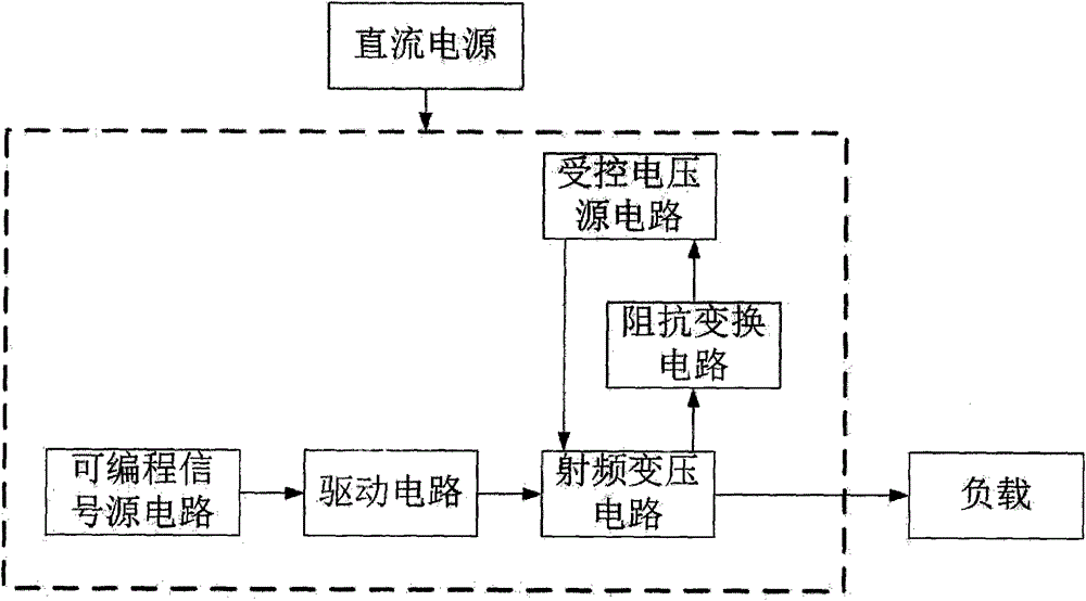
[0015] exist figure 1 Among them, the output terminal of the programmable signal source circuit is connected with the input terminal of the driving circuit, the output terminal of the driving circuit is connected with the input terminal of the radio frequency transformer circuit, and the output terminal of the radio frequency transformer circuit is connected with the input terminal of the impedance transformation circuit The other is connected to the load, the output end of the impedance transformation circuit is connected to the feedback end of the controlled voltage source circuit, the voltage output end of the controlled voltage source circuit is connected to the power input end of the radio frequency transformer circuit, each The block circuits are powered by a DC power supply.

[0016] In normal operation, the programmable signal source circuit outputs a high-fre...


PUM


Abstract

The invention discloses a mass spectrometer power circuit with adjustable radio frequency, which is formed by a programmable signal source circuit, a drive circuit, a radio frequency voltage transformation circuit, an impedance transformation circuit and a controlled voltage source circuit, and is characterized in that the programmable signal source circuit outputs a high-frequency signal, the high-frequency signal is amplified through the drive circuit to drive a switch tube of the radio frequency voltage transformation circuit, the on and the off of the switch tube can enable a high-frequency transformer connected with the switch tube to primarily produce periodic current change, and changed current is coupled through a radio-frequency transformer to secondary output. One path of high voltage output secondarily is transmitted to a load quadrupole rod and provides high-voltage radio-frequency voltage for the load quadrupole rod. The other path of the high voltage output secondarily is transmitted to the impedance transformation circuit. The impedance transformation circuit converts a high-voltage alternating current signal into a low-voltage direct current signal and transmits the low-voltage direct current signal to a feedback end of a controlled voltage source. A radio-frequency power supply can set the frequency of a signal source through software and adjust the output voltage of the controlled voltage source through a potentiometer so as to achieve the aim of controlling the frequency and the output voltage of the radio-frequency power supply.

Description

technical field [0001] The invention relates to an adjustable radio frequency power supply circuit of a mass spectrometer. By adjusting the output voltage of a controlled voltage source and the radio frequency frequency of a signal source in the circuit, the mass spectrometer can obtain different ion mass-to-charge ratios. Background technique [0002] A mass spectrometer is a chemical analysis instrument used for precise determination of molecular mass and compound analysis. The RF power supply is the core component of its circuit part. The RF power supply is the driving power for the quadrupole, ion trap or ion guide of the mass spectrometer. It outputs high-frequency AC power to generate an alternating electric field around the quadrupole, ion trap or ion guide of the mass spectrometer. The mass spectrometer controls the ions through the electric field or magnetic field and monitors the product movement to obtain the mass-to-charge ratio of the ions. [0003] At present...

Claims


Application Information

Patent Timeline
Patent Type & Authority Applications(China)
IPC IPC(8): H02M7/537
CPCH02M7/4807
Inventor 吕昱洲黄伟
Owner HEFEI INSTITUTES OF PHYSICAL SCIENCE - CHINESE ACAD OF SCI
Learn More