Condenser microphone and its impedance converter

A technology of condenser microphone and impedance converter, applied in the field of condenser microphone, can solve problems such as signal loss of capacitive voltage divider

Active Publication Date: 2015-06-03
GUANGDONG TAKSTAR ELECTRONIC CO LTD
View PDF6 Cites 2 Cited by
  • Summary
  • Abstract
  • Description
  • Claims
  • Application Information

AI Technical Summary

Problems solved by technology

[0015] (2) The leakage current of the JFET gate will flow through the large resistance bias resistor R2
[0016] (3) The leakage current caused by the pollution of the printed circuit

Method used


Image

  • Condenser microphone and its impedance converter
  • Condenser microphone and its impedance converter

Examples


Embodiment Construction

[0032] The preferred embodiments of the capacitive microphone and its impedance converter of the present invention will be further described below with reference to the accompanying drawings.

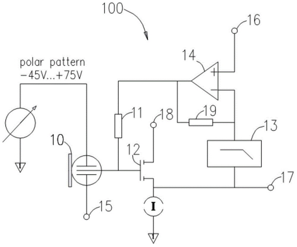
[0033] The capacitive microphone provided by the embodiment of the present invention, such as figure 1 As shown, it mainly includes a capacitive transducer 10 , a bias resistor 11 , an active element (JFET 12 in this embodiment), a low-pass filter 13 and an operational amplifier 14 . The active components are selected from JFET, MOSFET, transistor, electron tube, operational amplifier or a parallel circuit for impedance transformation formed by a combination thereof.

[0034] In this embodiment, the active element is an N-channel JFET, the gate of the JFET12 is directly connected to the capacitive transducer 10, and the drain of the JFET12 is connected to a DC voltage through the port 18 (usually applied twice the bias voltage on the JFET12), the source of the JFET12 is used as the ou...


PUM


Abstract

An condenser microphone is provided herein having an impedance converter directly coupled to the transducer of the condenser microphone. The impedance converter includes an active element for impedance conversion and a control circuit for filtering an AF output signal outputted from the active element in order to retrieve a bias direct voltage as a set value, the bias direct voltage being supplied to the other terminal of the bias resistor. A coupling capacitor between the condenser transducer and the active element is eliminated so that a bias resistor acting as a source of noise can be eliminated as well and the remaining bias resistor can be increased.

Description

technical field [0001] The present invention relates to condenser microphones using DC-coupled impedance conversion. Background technique [0002] For externally polarized condenser microphones, the change in transducer capacitance is related to the acoustic sound pressure on the transducer diaphragm (such as a singer's singing voice). In order to convert the change in capacitance into an electrical signal, the transducer is charged with a constant DC voltage to make it electrostatically charged. [0003] For a transducer with stable and constant static electricity, the relationship between its capacitance and capacitor voltage is: [0004] Uc=Qc / C [0005] Among them, Uc represents the DC voltage applied to the capacitor, Qc represents the electrostatic charge on the capacitor, and C represents the capacitance of the capacitor. [0006] The above relationship is only valid under the condition that the electrostatic charge Qc on the transducer remains constant. Therefore...

Claims


Application Information

Patent Timeline
IPC IPC(8): H04R19/04
CPCH04R3/00H04R19/04H04R2410/03
Inventor 不公告发明人
Owner GUANGDONG TAKSTAR ELECTRONIC CO LTD
Why Eureka
Try Eureka