Disordered automatic tube grabbing and inserting unit for small U-shaped tubes of fin assembly

A technology of U-shaped tubes and fins, which is applied in the field of air-conditioning manufacturing, can solve the problems of high labor intensity of operators, downtime and waiting for materials, and low utilization rate of equipment, so as to achieve a high degree of equipment automation, prevent quality accidents, and reduce labor intensity. Effect

Active Publication Date: 2015-06-10
XUZHOU DKEC ELECTRICAL TECH
View PDF7 Cites 4 Cited by
  • Summary
  • Abstract
  • Description
  • Claims
  • Application Information

AI Technical Summary

Problems solved by technology

[0007] 1. Due to the manual intubation operation, human factors such as the operator's sense of responsibility and emotion have a greater impact on the production progress, and because the previous tube expansion process is carried out by the tube expander, the efficiency is high, so in order to meet the follow-up The normal operation of the drying and welding process often requires multiple people to perform the manual intubation process, and the labor intensity of the operators is high and the efficiency is low;
[0008] 2. Although the front tube expansion process and the subsequent drying and welding process have been automated, the intubation process is still manually operated. Therefore, due to unreasonable personnel arrangements, too much output is often accumulated in the front process and the subsequent process When the process is shut down and waiting for materials, the degree of automation of the equipment is low, the utilization rate of the equipment is low, and the production capacity cannot be guaranteed;
[0009] 3. Since the intubation process is manual, it requires high skills and proficiency of the operators. The uneven operation proficiency of multiple operators also affects the production progress to varying degrees, and easily leads to unstable product quality.

Method used


Image

  • Disordered automatic tube grabbing and inserting unit for small U-shaped tubes of fin assembly
  • Disordered automatic tube grabbing and inserting unit for small U-shaped tubes of fin assembly
  • Disordered automatic tube grabbing and inserting unit for small U-shaped tubes of fin assembly

Examples


Embodiment Construction

[0032] The present invention will be further described below in conjunction with the accompanying drawings.

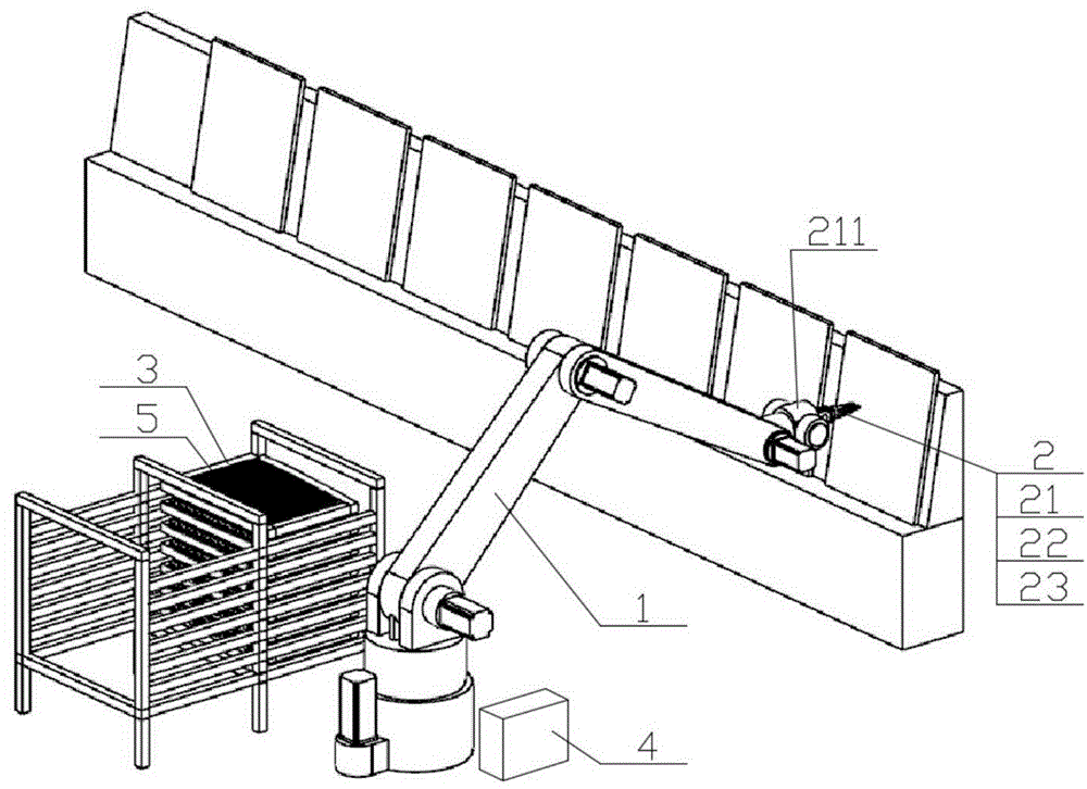
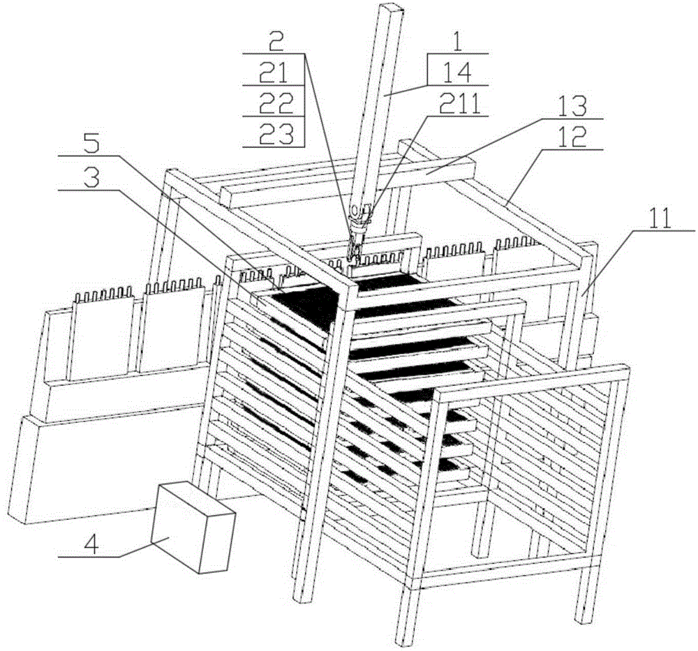
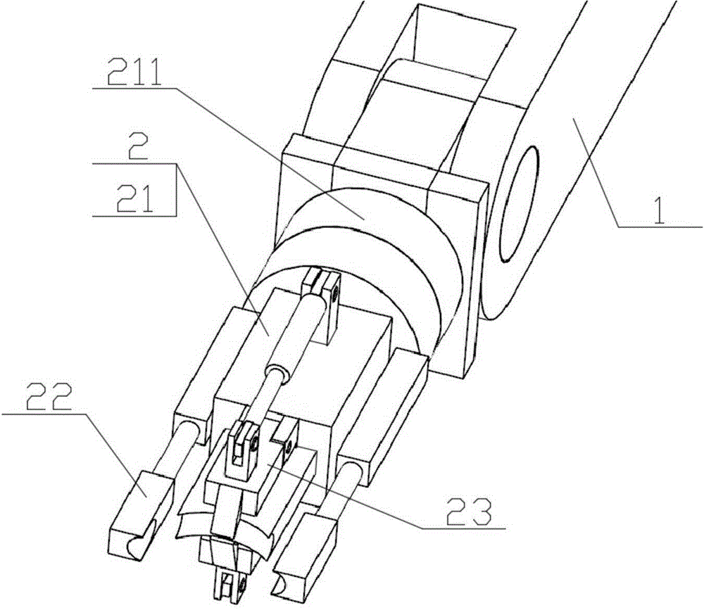
[0033] Such as Figure 1 to Figure 5 As shown, the small U-shaped tube of the fin assembly is disorderly and automatically grabs and intubates the unit including a mechanical arm 1, a manipulator 2, a small U-shaped tube carrying tray 3 and an electric control device 4 (the following description takes the left and right horizontal directions as X coordinates , the Y coordinate is the front and back horizontal direction, the Z coordinate is the vertical direction, the A coordinate is the rotation direction along the left and right horizontal axes, the B coordinate is the rotation direction along the front and rear horizontal axes, and the vertical axis is the rotation axis. The straight axis is the rotation axis and the direction of rotation is the C coordinate).

[0034] The mechanical arm 1 is fixedly installed on the ground, and includes an X-coordinate drive mechan...


PUM


Abstract

The invention discloses a disordered automatic tube grabbing and inserting unit for small U-shaped tubes of a fin assembly. The disordered automatic tube grabbing and inserting unit comprises a mechanical arm (1), a mechanical hand (2), small U-shaped tube bearing trays (3) and an electric control device (4), wherein the mechanical arm is fixedly mounted on the ground and comprises an X-coordinate drive mechanism, a Y-coordinate drive mechanism and a Z-coordinate drive mechanism; the mechanical hand comprises a main body (21), two clamping fingers (22) and two supporting fingers (23); a top end of the main body is connected with a tail end of the mechanical arm through a mounting seat (211); a C-coordinate drive mechanism is arranged in the mounting seat; arc-shaped grooves matched with outer diameters of the small U-shaped tubes (5) and radians of U shapes are formed in a bottom end surface of the main body and inner side surfaces of the clamping fingers; the distance between an upper surface of each supporting finger and the bottom of each arc-shaped groove is matched with the size of each small U-shaped tube. The tube inserting unit can realize automated operation, reduce influence of human factors on a production progress and guarantee the product quality in a tube insertion process.

Description

technical field [0001] The invention relates to a fin assembly automatic intubation unit, in particular to an automatic grasping and insertion of small U-shaped tubes of the fin assembly in the process of inserting the fin assembly of the radiator and condenser of the air conditioner. A tube unit belongs to the technical field of air conditioner manufacturing. Background technique [0002] Usually, metal sheets with strong thermal conductivity are added on the surface of the heat exchange device that requires heat transfer to increase the heat exchange surface area of ​​the heat exchange device and improve the heat exchange efficiency. The metal sheets with this function are called fins. [0003] There are two main heat exchangers in the air conditioner, namely the radiator and the condenser. The working medium of these two heat exchangers is refrigerant on one side and air on the other side. In order to enhance the heat transfer of the heat exchanger, generally The heat ex...

Claims


Application Information

Patent Timeline
Patent Type & Authority Applications(China)
IPC IPC(8): B23P19/00
CPCB23P19/007
Inventor 郝新浦
Owner XUZHOU DKEC ELECTRICAL TECH
Why Eureka
Try Eureka