
Self-lifting sliding and turnover construction system and construction method

A construction method and self-lifting technology, applied in the direction of erecting/assembling bridges, bridges, buildings, etc., can solve the problems of high labor intensity of slip-form construction workers, affecting construction quality, and high physical energy consumption of workers, so as to reduce the cost of manual mold overturning. Risks, reducing labor intensity of workers, and the effect of low labor intensity of workers

Active Publication Date: 2015-06-10
CCCC FIRST HIGHWAY XIAMEN ENG +1
View PDF7 Cites 21 Cited by
  • Summary
  • Abstract
  • Description
  • Claims
  • Application Information

AI Technical Summary

Problems solved by technology

[0006] The surface quality of slipform construction structures is poor. Due to the technical characteristics of the slipform construction method, the steel formwork must constantly rub the concrete surface during construction, and there are inevitably gaps between the steel formwork and the concrete, which makes the cement produced by concrete vibration The slurry will flow down the side wall of the pier and pollute the apparent quality of the pier
[0007] Slipform construction workers are labor-intensive. Since slipform construction is continuous construction, workers must work almost without interruption, which consumes a lot of physical energy, especially in summer, which is prone to heatstroke and other situations.
[0008] Slipform construction is prone to decrease in the quality of steel bar binding. Since slipform construction is uninterrupted construction, sometimes in order not to affect the construction period, when the supervision is not in place, problems such as unqualified steel bar spacing will occur, which will affect the construction quality.

Method used


Image

  • Self-lifting sliding and turnover construction system and construction method
  • Self-lifting sliding and turnover construction system and construction method
  • Self-lifting sliding and turnover construction system and construction method

Examples


Embodiment Construction

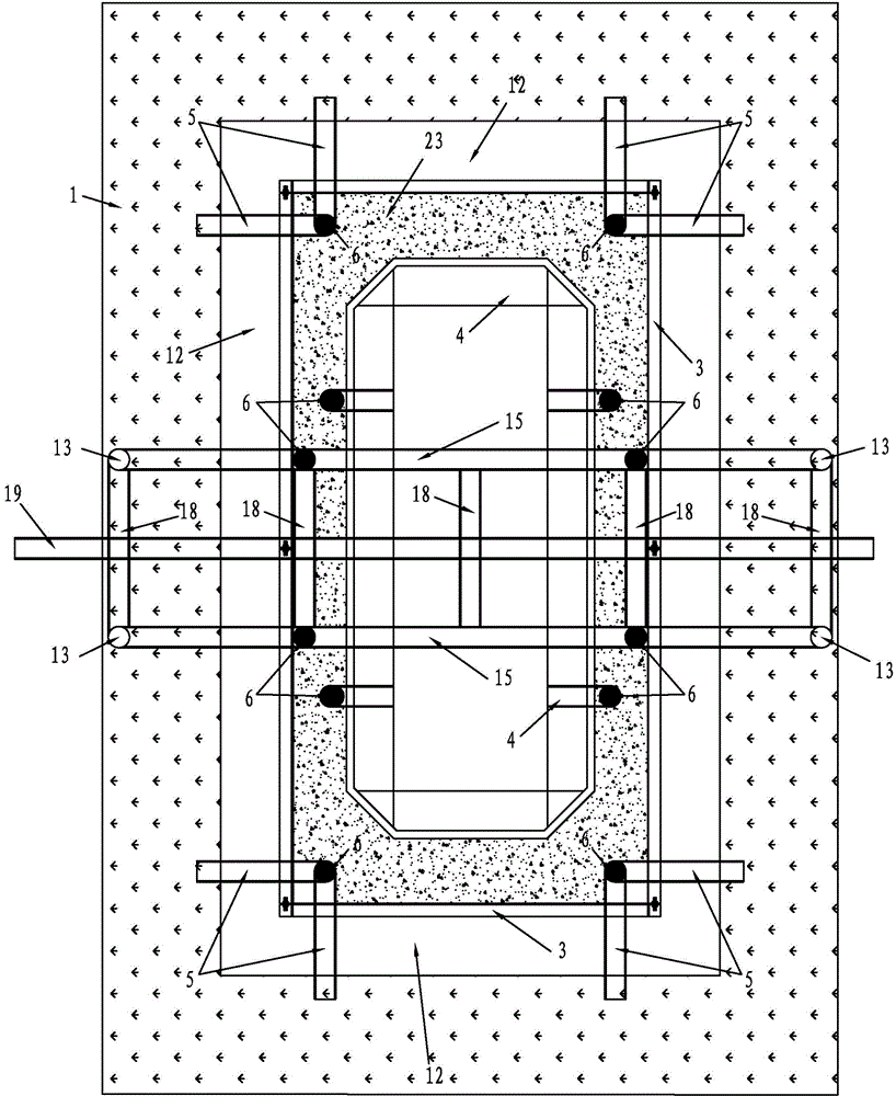
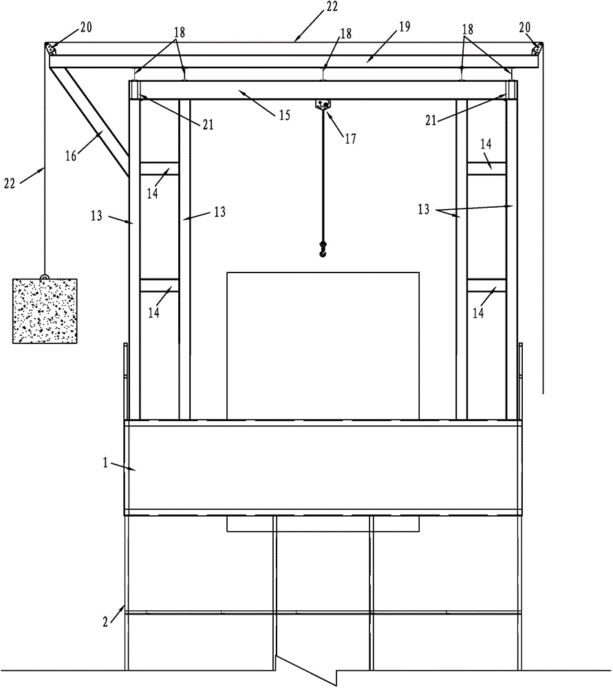
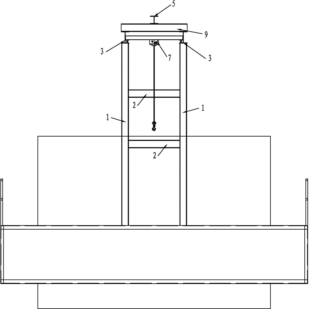
[0080] see figure 1 , in the present embodiment, the building body 23 is rectangular, and the self-elevating sliding system of the present invention includes an outer mold working disk 1 surrounding the outer periphery of the building body 23, and the bottom of the outer mold working disk 1 is provided with a double-layer auxiliary working disk 2, There is a certain distance between the inner side of the outer mold working disk 1 and the outer side of the building body 1 , and this distance is reserved for the hoisting channel 12 . A large-area steel formwork 3 is arranged close to the outside of the building body 23, and an inner mold sliding formwork frame 4 is arranged on the inside of the building body 3,

[0081] The self-elevating sliding turning system of the present invention includes a frame-type combined crane hanger device and a semi-automatic mold turning device. Among them, the frame-type combined crown crane hanger device spans the entire outer mold working plat...


PUM


Abstract

The invention discloses a self-lifting sliding and turnover construction system and a construction method. The system comprises a framework type combination crown block hanging bracket device and a semi-automatic turnover device. The construction method comprises steps as follows: construction of reinforcing steel bars of a pier body, large-area formwork bracket splicing, sliding formwork bracket splicing, self-lifting hanging bracket splicing, concrete pouring, sliding formwork bracket sliding rising, large-area formwork turnover and next stage of reinforcing steel bar construction. A self-lifting technique can be adopted, auxiliary construction by mechanical equipment such as a tower crane, a truck crane and the like can be omitted, high-pier construction is realized with the self-lifting technique, and the method guarantees the construction speed of a sliding formwork and the appearance quality of a turnover formwork without relying on external machines.

Description

technical field [0001] The invention belongs to the field of bridge construction, and in particular relates to a self-elevating and slipping construction method. Background technique [0002] my country's highway industry is changing with each passing day. For regional economic development, more expressways extend into deep mountains, or cross rivers, lakes, rivers and seas. Therefore, the design of high piers in bridge engineering is very common. At present, there are usually three types of high pier construction in my country: turning formwork, sliding formwork, and climbing formwork. In view of the high construction technology requirements and high construction costs of climbing formwork, climbing formwork is mostly used in super-large bridge main pier projects, and the number is more Many ordinary high piers are usually constructed by overturning or sliding form. However, the overturning and sliding form construction methods have the following problems: [0003] The ov...

Claims


Application Information

Patent Timeline
IPC IPC(8): E01D21/00
Inventor 孟源王铁法张良荣牛海喜黄雄飞吕爽王殿会甘烈火黄宇郝欣欣
Owner CCCC FIRST HIGHWAY XIAMEN ENG
Learn More