Hydraulic control system for hydraulic drive cutting table and elevator

A technology of hydraulic control system and elevator, which is applied in the safety of fluid pressure actuation system, components of fluid pressure actuation system, and fluid pressure actuation device, etc., can solve installation and maintenance difficulties, high failure rate, transmission device It can solve problems such as complex structure, and achieve the effect of solving foreign body blockage, improving work efficiency and simplifying the transmission system of the whole machine.

Inactive Publication Date: 2015-06-10
JIANGSU NONGHUA WISDOM AGRICULTURAL SCIENCE AND TECHNOLOGY CO LTD
View PDF7 Cites 6 Cited by
  • Summary
  • Abstract
  • Description
  • Claims
  • Application Information

AI Technical Summary

Problems solved by technology

[0002] At present, the operation of corn harvester header and elevator is generally driven by mechanical transmission (such as belt drive and chain drive), and it needs to go through multi-stage deceleration to transmit power to the header and elevator. drive shaft, which leads to complex structure of the transmission device, difficult installation and maintenance, and high failure rate

Method used


Image

  • Hydraulic control system for hydraulic drive cutting table and elevator
  • Hydraulic control system for hydraulic drive cutting table and elevator

Examples


Embodiment Construction

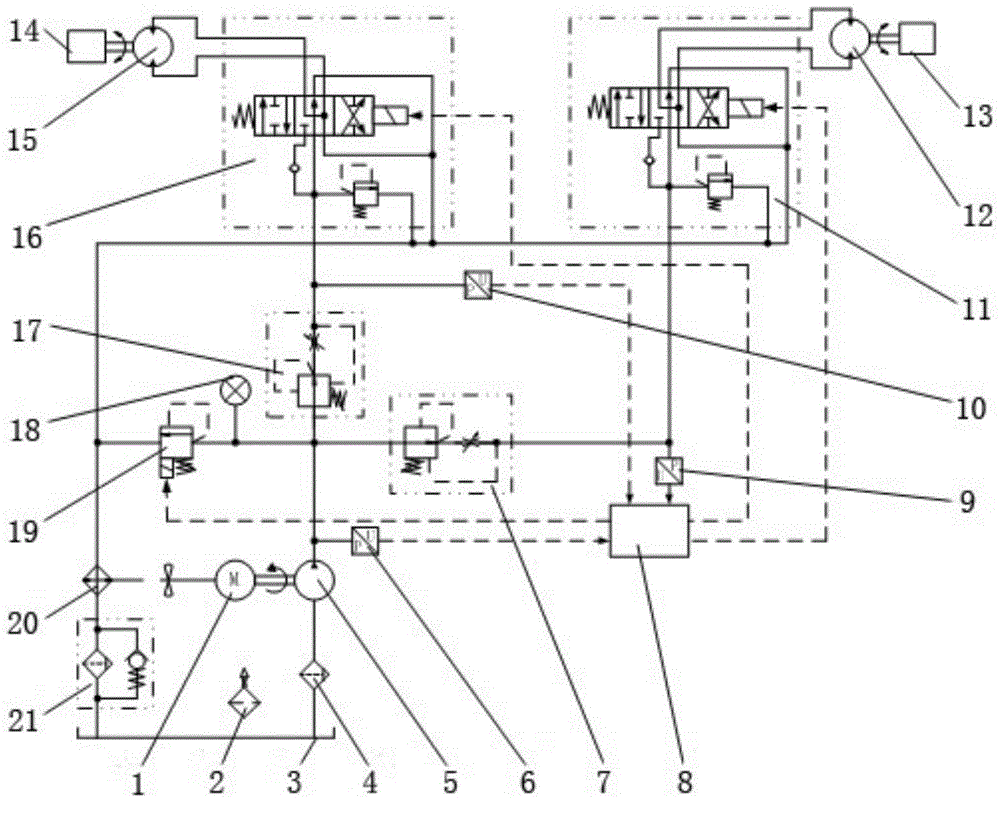
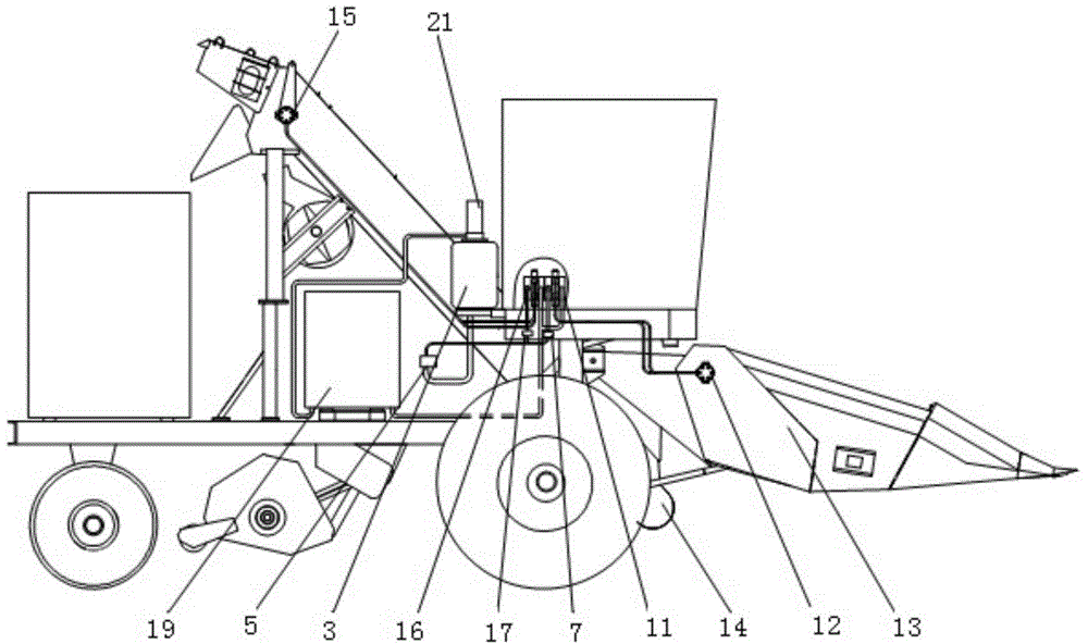
[0015] See figure 1 with figure 2 It can be seen that the present invention includes engine 1, air filter 2, hydraulic oil tank 3, oil suction filter 4, gear pump 5, No. 1 pressure sensor 6, No. 1 pressure compensation valve 7, controller 8, No. 2 pressure sensor 9, and No. 3 pressure sensor. No. 1 pressure sensor 10, No. 1 reversing valve 11, No. 1 hydraulic motor 12, header 13, elevator 14, No. 2 hydraulic motor 15, No. 2 reversing valve 16, No. 2 pressure compensation valve 17, overflow valve 19. Air-cooled radiator 20, oil return filter 21; the engine 1 is connected to the gear pump 5, the oil suction filter 4 is arranged at the oil outlet at the bottom of the hydraulic oil tank 3, and the oil outlet of the oil suction filter 4 is connected to the The oil inlet of the gear pump 5 is connected; the oil outlet of the gear pump 5 is respectively connected with the oil inlets of the relief valve 19, the No. 1 pressure compensation valve 7 and the No. 2 pressure compensation ...


PUM


Abstract

The invention relates to a hydraulic control system for a hydraulic drive cutting table and an elevator. The hydraulic control system comprises an engine, a hydraulic oil tank, a gear pump, a pressure sensor I, a pressure compensation valve I, a controller, a pressure sensor II, a pressure sensor III, a reverse valve I, a hydraulic motor I, the cutting table, the elevator, a hydraulic motor II, a reverse valve II, a pressure compensation valve II and an overflow valve, wherein intelligence of harvester operation is realized through oil path connection and under the control of the controller. The hydraulic control system simplifies a transmission system of a complete machine and improves the working efficiency of the machine.

Description

technical field [0001] The invention relates to a hydraulic control system on agricultural machinery, in particular to a hydraulic control system for hydraulically driving headers and elevators. Background technique [0002] At present, the operation of corn harvester header and elevator is generally driven by mechanical transmission (such as belt drive and chain drive), and it needs to go through multi-stage deceleration to transmit power to the header and elevator. The drive shaft of the drive shaft leads to a complex structure of the transmission device, difficult installation and maintenance, and a high failure rate. Contents of the invention [0003] The purpose of the present invention is to provide a hydraulic control system for a hydraulically driven header and an elevator with a simple transmission system, high working efficiency and certain intelligence. [0004] The technical solution for realizing the object of the present invention is: the present invention c...

Claims


Application Information

Patent Timeline
Patent Type & Authority Applications(China)
IPC IPC(8): F15B11/16F15B13/06F15B20/00F15B21/04A01D69/06A01D69/03
CPCF15B11/16A01D69/03A01D69/06F15B13/06F15B20/005F15B21/041F15B21/042F15B2211/40576F15B2211/615F15B2211/62F15B2211/78F15B2211/857
Inventor 申屠军阳荆毅付颜红
Owner JIANGSU NONGHUA WISDOM AGRICULTURAL SCIENCE AND TECHNOLOGY CO LTD
Why Eureka
Try Eureka