
A connection seat for heliostats in a tower-type solar thermal power station

A tower-type solar energy and connection seat technology, which is applied in the direction of solar thermal power generation, solar thermal devices, heating devices, etc., can solve the problems of high probability of damage to the connection seat and high replacement cost, and achieve cost savings, low maintenance costs, and reduced post-maintenance cost effect

Active Publication Date: 2017-01-18
ZHEJIANG SUPCON SOLAR TECHNOLOGY CO LTD
View PDF6 Cites 0 Cited by
  • Summary
  • Abstract
  • Description
  • Claims
  • Application Information

AI Technical Summary

Problems solved by technology

[0007] The purpose of the present invention is to provide a connection seat for the heliostat of a tower-type solar thermal power station, so as to solve the problems of high damage probability and high replacement cost of the existing connection seat proposed in the background technology

Method used


Image

  • A connection seat for heliostats in a tower-type solar thermal power station
  • A connection seat for heliostats in a tower-type solar thermal power station
  • A connection seat for heliostats in a tower-type solar thermal power station

Examples


Embodiment 1

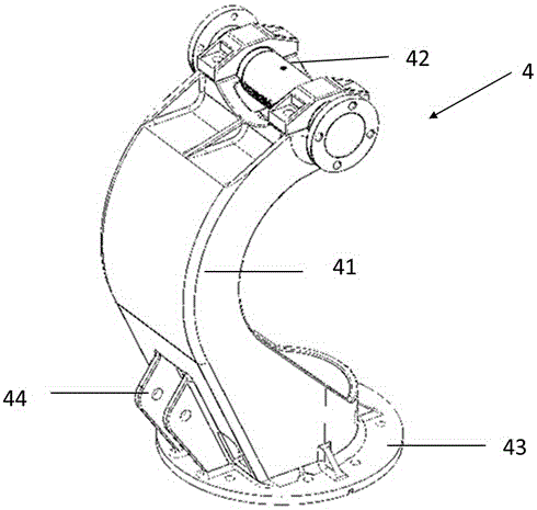
[0050] Such as image 3As shown, the connecting seat 4 provided by the present invention includes a connecting seat body 41 , a bearing component 42 , a connecting seat flange 43 and a header pin mounting hole 44 . Wherein, the connection seat body 41 is an arc-shaped support member. In other preferred embodiments, the connection seat body 41 can be a support member with one side sunken inward, and the shape of the depression can be semicircular, “concave” or Any other structural shape can accommodate the support of the main beam 121 of the mirror bracket 12; the head pin mounting hole 44 is located on the arc back of the connecting seat body 41, and the head pin mounting hole 44 is used for the horizontal angle driving device with the mirror body 1 2 are connected, and the elevation angle rotation of the mirror body 1 can be controlled by the horizontal angle driving device 2; the connecting seat flange 43 is located at the bottom of the connecting seat body 41, and the conne...

Embodiment 2

[0060] In this embodiment, except the following part of the structure is different from the first embodiment, other parts of the structure and parameters are the same as the first embodiment. The differences are as follows:

[0061] Such as Figure 10 , Figure 11 As shown, the bearing component 42 in this embodiment includes a bearing 421 , a horizontal shaft 422 , and a sleeve 424 . The sleeve 424 is sheathed on the outside of the bearing component 42 and inside the hoop. Two ends of the sleeve 424 are provided with sealing rings 423 . In addition, the sleeve 424 is also provided with a vent plug 48 , and the vent plug 48 is also used to inject lubricating oil into the bearing 421 , and at the same time discharge the gas in the sleeve 424 to facilitate the assembly of the entire bearing component 42 .

[0062] The setting of the sleeve 424 can further protect the bearing 421, and the setting of the sealing ring 423 forms a sealed environment in the sleeve 424, which can m...


PUM


Abstract

The invention provides a connecting seat for a heliostat of a tower-type solar thermal power station. The connecting seat reduces the friction between the rotating shaft when the rotating shaft rotates by setting a bearing between the hoop and the rotating shaft, so that the rotating shaft rotates more smoothly. smooth. The addition of the sleeve and the sealing ring outside the bearing makes the shaft and the bearing in a relatively closed space, avoiding the long-term exposure of the flange shaft as the shaft to the air, and avoiding the flange caused by corrosion and falling dust. Shaft wear. The connection seat does not need to be coated, and does not need to be frequently disassembled to renew the coating, and the maintenance cost is low. The hoop and the connecting seat are integrally structured, and the overall supporting capacity of the connecting seat structure is good. At the same time, because the hoop only plays the role of fixing the bearing, the manufacturing precision requirements for the upper and lower gussets are low. A pair of protruding parts with head pin mounting holes extend downward to the flange of the connecting seat and are integrated with the flange of the connecting seat, which can enhance the strength of the joint between the flange of the connecting seat and the push rod.

Description

technical field [0001] The invention relates to a heliostat structural component in the field of solar power generation, in particular to a connection seat for a heliostat of a tower-type solar thermal power station. Background technique [0002] While the economy continues to develop, energy is increasingly in short supply, traditional non-renewable energy is increasingly exhausted, and economic development is increasingly restricted by the development and utilization of energy. The utilization of renewable energy has attracted widespread attention, especially solar energy. [0003] The current solar thermal power generation can be divided into (1) tower solar power generation; (2) trough solar thermal power generation; (3) dish solar thermal power generation according to the solar energy collection method [0004] In the field of photothermal power generation, tower-type solar thermal power generation has the advantages of high photothermal conversion efficiency, high focu...

Claims


Application Information

Patent Timeline
Patent Type & Authority Patents(China)
IPC IPC(8): F24J2/54G02B7/198
CPCY02E10/47
Inventor 张旭中江远财黄圆明谭潇陈康立王伊娜胡中
Owner ZHEJIANG SUPCON SOLAR TECHNOLOGY CO LTD
Learn More