Heat pump dryer

A dryer and heat pump technology, applied in dryers, drying, local stirring dryers, etc., can solve the problems of backward drying equipment technology, long construction period, inconvenient debugging, etc., to save material costs and construction costs , Good energy-saving effect, convenient installation and disassembly

Inactive Publication Date: 2015-06-10
宁夏塞上阳光新能源科技有限公司
View PDF9 Cites 4 Cited by
  • Summary
  • Abstract
  • Description
  • Claims
  • Application Information

AI Technical Summary

Problems solved by technology

[0004] The purpose of the present invention is to solve the problems of backward drying equipment technology, inconvenient installation, long construction period and inconvenient debugging in the drying room, and provide a new type of closed heat pump dryer with dehumidification function

Method used


Image

  • Heat pump dryer
  • Heat pump dryer
  • Heat pump dryer

Examples


Embodiment 1

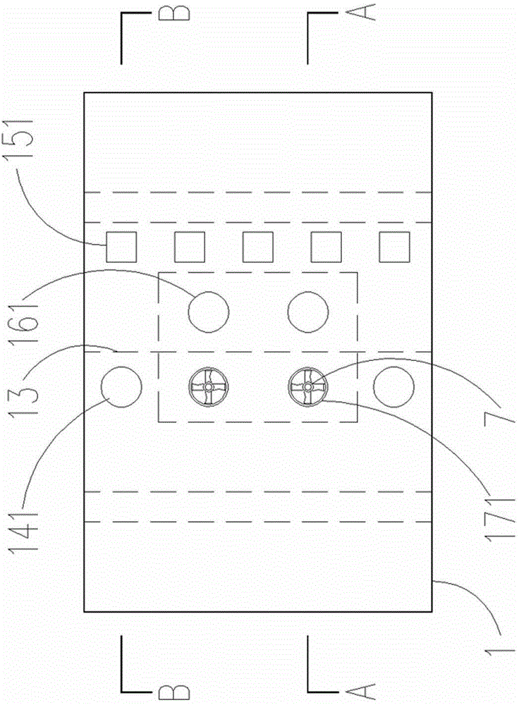
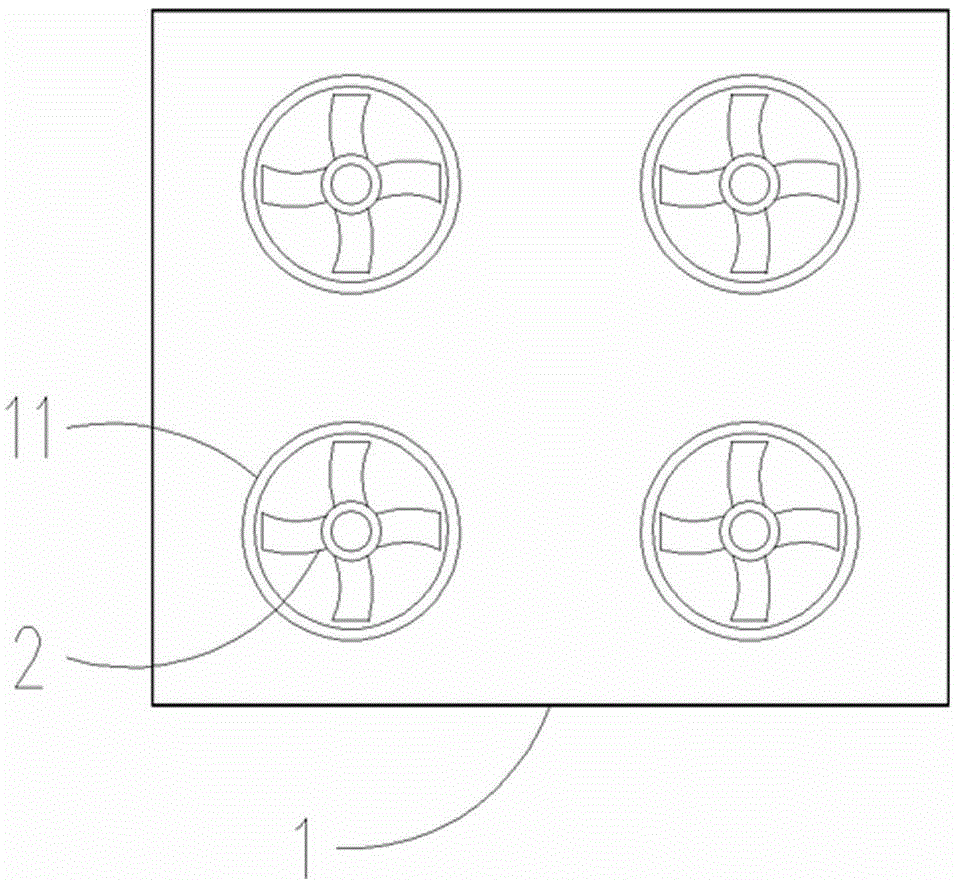
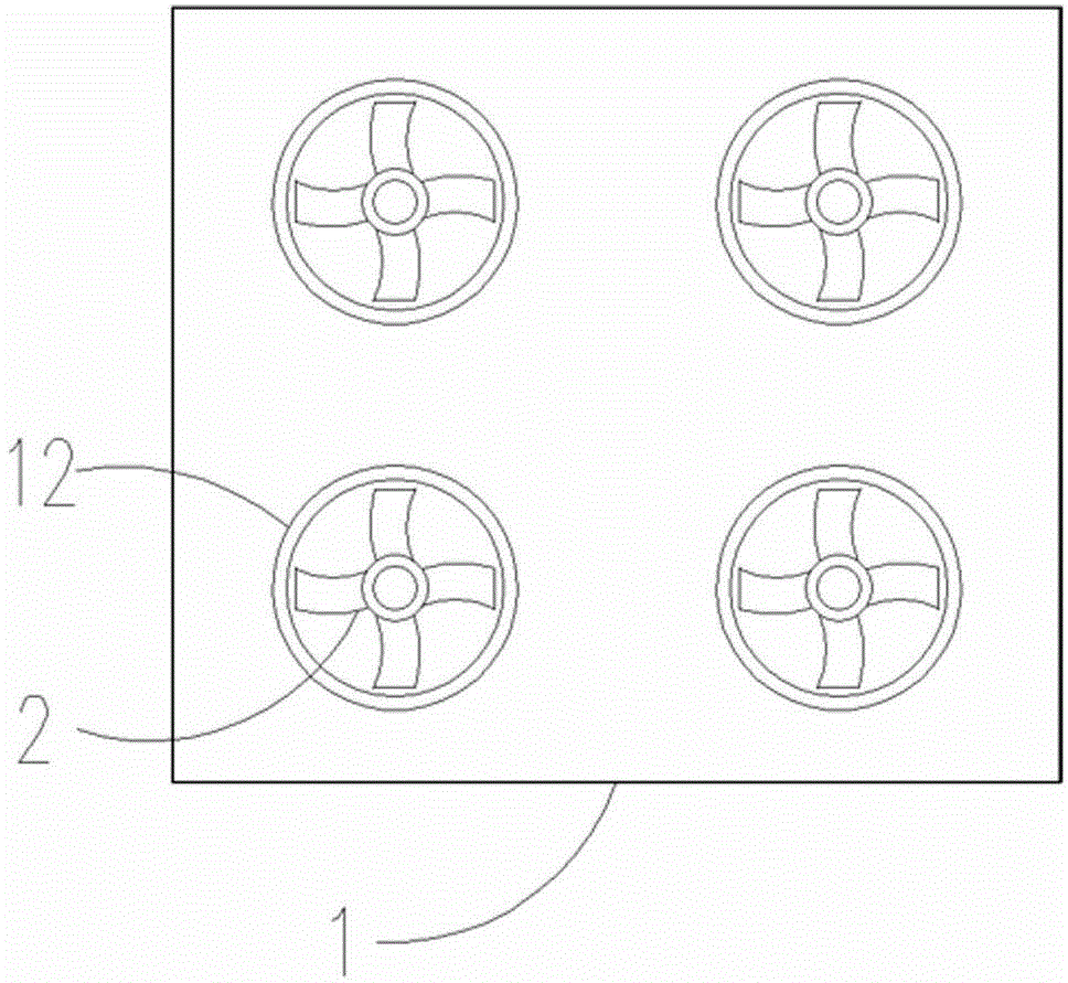
[0031] As attached Figure 7 As shown, the indoor air heating method of the heat pump dryer of the present invention: Turn on the fan 2 at the indoor circulation fan port 11 and the outdoor circulation fan port 12, and the outdoor hot air enters the outdoor air collector 15 through the air hole 151 and passes through the evaporator 5. Blow out from the outdoor circulation fan port 12; indoor air enters the indoor air heating chamber 14 through the indoor air circulation port 141, passes through the condenser 4, and blows into the room from the indoor circulation fan port 11. Turn on the air compression pump 6, the heat exchange medium in the air heat source heating system absorbs heat and vaporizes in the evaporator 5, compresses it into high temperature gas by the compression pump, and then circulates to the condenser 4 to release heat into low temperature gas, and finally Circulate to the evaporator to absorb heat; when the indoor air passes through the condenser 4 in the indo...

Embodiment 2

[0033] As attached Figure 8 As shown, the exhaust dehumidification process of the heat pump dryer of the present invention: when the indoor air humidity exceeds a specified value, the ventilation fan 7 installed on the exhaust port 171 of the exhaust cavity 17 is started to pass the indoor hot and humid air The exhaust cavity 17 passes through the hot air cavity of the air heat exchanger 3 and is discharged into the outdoor air heat collecting chamber 15, and finally blown out from the outdoor circulation fan port 12 of the outdoor air heat collecting chamber 15; at the same time, the effect of the negative pressure inside and outside The outdoor dry air is sucked in from the air inlet 161 of the air inlet cavity 16, passes through the cold air cavity of the air heat exchanger 3, enters the indoor air heating chamber 14, and enters the drying room after being heated by the condenser 4; 3Using the temperature of the exhausted hot and humid gas to preheat the added dry air to ac...


PUM


Abstract

The invention relates to a heat pump dryer used in a storage drying chamber for cereals, medlar, medical materials and the like in agricultural production. The heat pump dryer is formed by fixedly combining and installing a box body, a blower, an air heat exchanger, a condenser and an evaporator; the box body is the closed box-type structure, the interior is divided to the front and rear closed independent indoor air heating chamber and outdoor air heat collecting chamber by a baffle, and the top is provided with an air inlet cavity and an air discharging cavity; the top of the indoor air heating chamber is uniformly provided with indoor air circulating ports; an indoor circulation blower port and an outdoor circulation blower port are respectively and independently provided with blowers fixedly; the middle of the baffle is provided with the air heat exchanger; the indoor air heating chamber is internally provided with the condenser fixedly; and the outdoor air heat collecting chamber is internally provided with the evaporator and an air compressor pump fixedly. The heat pump dryer has the beneficial effects of convenient installing and detaching, and good heating, dehumidifying and energy-saving effects, is capable of saving the material cost and the construction cost of a drying house, and shortening the building period of the drying house, so the technology of the drying house is more easily popularized.

Description

technical field [0001] The invention belongs to the technical field of drying equipment, and in particular relates to a large drying equipment used in a storage drying room for grains, wolfberries, medicinal materials and the like in agricultural production. Background technique [0002] With the development of agricultural production and industrialization equipment, indoor drying technology has become an indispensable means to promote the process of agricultural industrialization. In agricultural production, many agricultural products such as rice, wheat, corn, wolfberry, and medicinal materials need to be dried and dried. However, the ordinary drying time is long and the number of times of drying is high, resulting in long production cycle and high labor costs. A stumbling block to the process. Under this background, the drying room technology has played an important role in solving the drying and drying technology. [0003] At present, in the market, the drying room u...

Claims


Application Information

Patent Timeline
Patent Type & Authority Applications(China)
IPC IPC(8): F26B9/06F26B21/02
Inventor 罗予罗子涵
Owner 宁夏塞上阳光新能源科技有限公司
Why Eureka
Try Eureka