motor control unit
A motor control and speed control technology, applied in motor control, single motor speed/torque control, control system, etc., can solve the problems of lack of traceability, difficulty in improving the cut-off frequency of the torque filter, etc. sexual effect
- Summary
- Abstract
- Description
- Claims
- Application Information
AI Technical Summary
Problems solved by technology
Method used
Image
Examples
Embodiment approach 1
[0040]
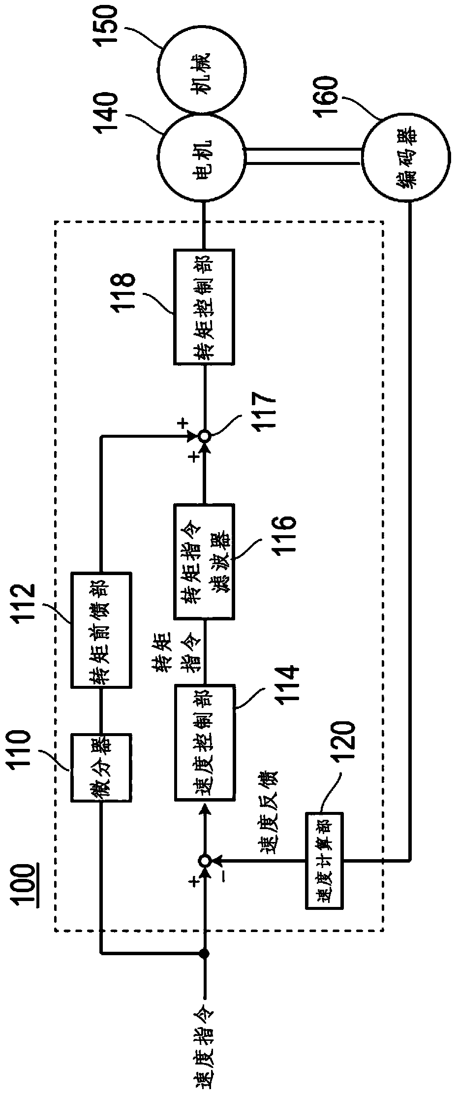
[0041] figure 1 It is a block diagram of the motor control device of Embodiment 1. The motor control device 100 of the present embodiment includes a differentiator 110 , a torque feedforward unit 112 , a speed control unit 114 , a torque command filter 116 , a torque control unit 118 , and a speed calculation unit 120 .
[0042] The feedforward system of the motor control device 100 includes a differentiator 110 and a torque feedforward unit 112 . The differentiator 110 differentiates the speed command input to the motor control device 100 . The torque feedforward unit 112 calculates (generates) a torque command (first torque command) of the feedforward system based on the differentiated speed command.
[0043] In this way, the first torque command for the feedforward system is directly calculated from the speed command. Therefore, the first torque command does not contain mechanical resonance and quantization fluctuations of the encoder.
[0044] The speed cont...
Embodiment approach 2
[0058]
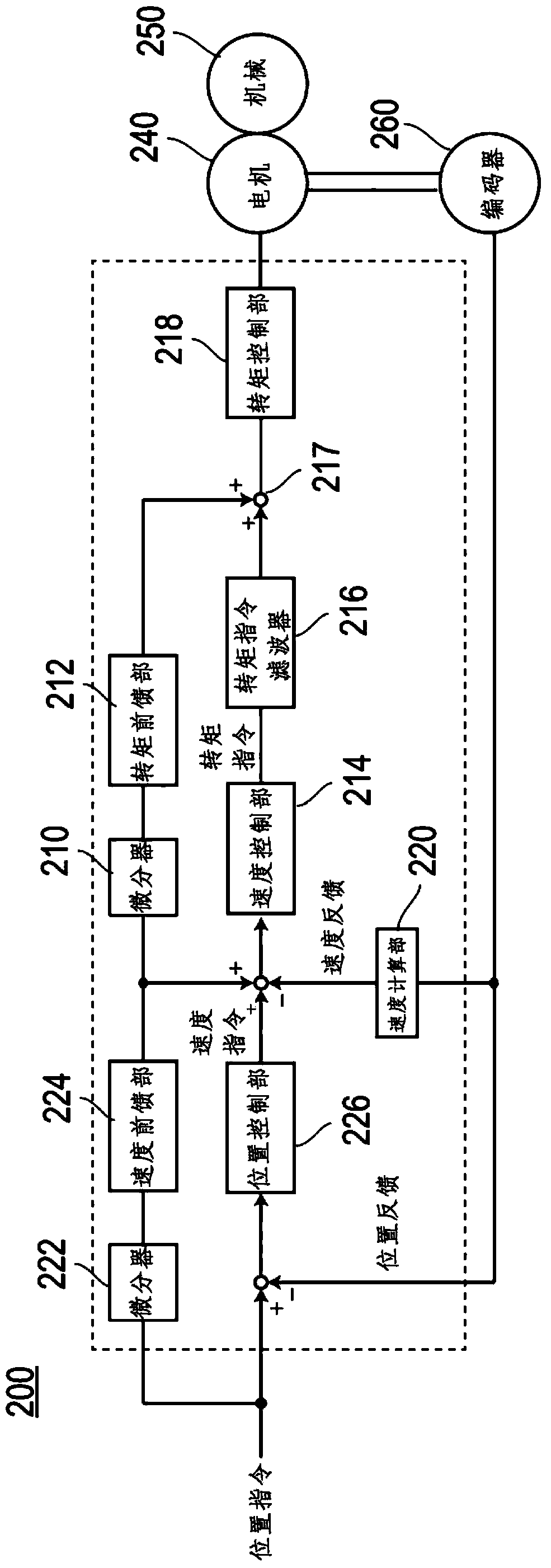
[0059] image 3 It is a block diagram of the motor control device of Embodiment 2. The motor control device 200 of the present embodiment includes a differentiator 222 (first differentiator), a speed feedforward unit 224 , and a position control unit 226 in addition to the same components as the motor control device 100 of the first embodiment.
[0060] The differentiator 210 (second differentiator), the torque feedforward unit 212, the speed control unit 214, the torque command filter 216, the torque control unit 218, and the speed calculation unit 220 of the motor control device 200 of the present embodiment are respectively Differentiator 110 , torque feedforward unit 112 , speed control unit 114 , torque command filter 116 , torque control unit 118 , and speed calculation unit 120 have substantially the same functions as those of motor control device 100 according to Embodiment 1. In addition, the torque feedforward in this embodiment is calculated from the spe...
Embodiment approach 3
[0080]
[0081] Figure 5It is a block diagram of the motor control device of Embodiment 3. The motor control device 300 of the present embodiment has substantially the same configuration as the motor control device 100 of the first embodiment except that the feedforward system is constituted by the mode controller 370 . The speed control unit 314, the torque command filter 316, the torque control unit 318, and the speed calculation unit 320 of the motor control device 300 according to the present embodiment respectively have a The torque command filter 116, the torque control unit 118, and the speed calculation unit 120 have substantially the same functions.
[0082] Here, the motor control device 300 of the present embodiment employed in a speed control device using a mode controller will be described. The mode controller 370 constitutes a speed control system obtained by modeling the motor control device 100 , the motor 140 , the machine 150 , and the encoder 160 accord...
PUM
 Abstract
Description
Claims
Application Information
 - R&D
- Intellectual Property
- Life Sciences
- Materials
- Tech Scout
- Unparalleled Data Quality
- Higher Quality Content
- 60% Fewer Hallucinations
Browse by: Latest US Patents, China's latest patents, Technical Efficacy Thesaurus, Application Domain, Technology Topic, Popular Technical Reports.
© 2025 PatSnap. All rights reserved.Legal|Privacy policy|Modern Slavery Act Transparency Statement|Sitemap|About US| Contact US: help@patsnap.com


