Synchronous traction engine system and device

A traction machine and synchronous control technology, which is applied in the directions of transportation and packaging, object supply, and object delivery, can solve the problems of PID controller parameter setting defects, etc., and achieve the effects of convenient maintenance, improved accuracy, and increased clearance

Inactive Publication Date: 2015-06-17
QINGDAO HENGBO INSTR
View PDF6 Cites 0 Cited by
  • Summary
  • Abstract
  • Description
  • Claims
  • Application Information

AI Technical Summary

Problems solved by technology

However, the parameter setting of the PID controller of this synchronous device has certain defects.

Method used


Image

  • Synchronous traction engine system and device
  • Synchronous traction engine system and device
  • Synchronous traction engine system and device

Examples


Embodiment Construction

[0043] The implementation of the present invention will be described in detail below in conjunction with the examples, so as to fully understand and implement the implementation process of how to apply technical means to solve technical problems and achieve technical effects in the present invention.

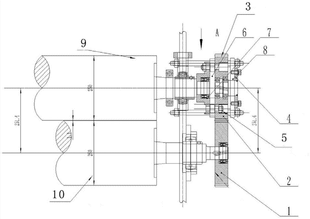
[0044] The invention relates to an up and down synchronous drive hollow plate tractor, including upper and lower rollers; upper and lower gears; intermediate gears, various bearings; The tractor of the active system of the present invention drives the sprocket through the reducer, the sprocket drives the lower roller, the lower roller drives the lower gear, and then the lower gear drives the upper gear to realize synchronous transmission up and down. The gear of the upper roller is added, mainly to improve the traction force of the tractor and the friction gap.

[0045] In addition, the present invention further has an optional lower roller power drive system and a hydraulic syn...


PUM


Abstract

The invention discloses a synchronous traction engine system. The synchronous traction engine system comprises an upper roller, a lower roller, gears, a gear shaft, a connecting disc and a cross joint. The synchronous traction engine system is characterized by being provided with a driven system; the driven system directly drives the lower roller, the lower roller drives the lower gear, and then the lower gear drives the upper gear to achieve vertically synchronous transmission. The number of the gears is three, the gear I rotates rightwards, the gear III rotates leftwards, and the number of teeth of the gear II is 20-40 and is preferably 31; the modulus of the gear I and the modulus of the gear II are both 2-10 and are preferably 8. The synchronous traction engine system overcomes the defects of an existing hollow plate traction engine, works in a vertical transmission mode, and enables the upper roller and the lower roller to achieve completely synchronous transmission while a speed reducer drives, thereby guaranteeing non-slip of traction through continuous synchronization, increasing frictional force, greatly improving production efficiency, increasing errors between a bevel gear and a rolling shaft, and improving transmission performance.

Description

technical field [0001] The invention relates to a traction mechanism system, in particular to a synchronous traction machine system and device. Background technique [0002] At present, only the lower roll is powered, and the upper roll is passive in many hollow plate tractors in the prior art. Because a reducer drives the sprocket, and then drives the teeth of the lower roller to rotate, the upper roller cannot be pressed very tightly with the lower roller during work, and the compression is easy to cause deformation of the hollow plate. This has caused the upper roller to slip when it cannot be pressed tightly, and the lower transmission gear is a spur gear, the transmission gap is relatively large, and errors follow. [0003] And some hollow plate tractors in the prior art also have the dual power drive system that upper and lower rollers have power respectively, and corresponding synchronizing device thereof. However, the parameter setting of the PID controller of this...

Claims


Application Information

Patent Timeline
Patent Type & Authority Applications(China)
IPC IPC(8): B65H79/00B65H5/06B65H29/20
Inventor 不公告发明人
Owner QINGDAO HENGBO INSTR
Why Eureka
Try Eureka