Laser self-blending grating interferometer and measuring method thereof

A grating interference and self-mixing technology, used in measuring devices, instruments, optical devices, etc., can solve the problems of complex structure and difficult adjustment of optical path, and achieve the effect of large measurement range, strong anti-interference, and convenient adjustment of optical path.

Inactive Publication Date: 2015-06-17
NANJING NORMAL UNIVERSITY
View PDF8 Cites 15 Cited by
  • Summary
  • Abstract
  • Description
  • Claims
  • Application Information

AI Technical Summary

Problems solved by technology

However, the optical path of the existing grating interferometer contains multiple photodetectors, polarization beam

Method used


Image

  • Laser self-blending grating interferometer and measuring method thereof
  • Laser self-blending grating interferometer and measuring method thereof
  • Laser self-blending grating interferometer and measuring method thereof

Examples


Embodiment 1

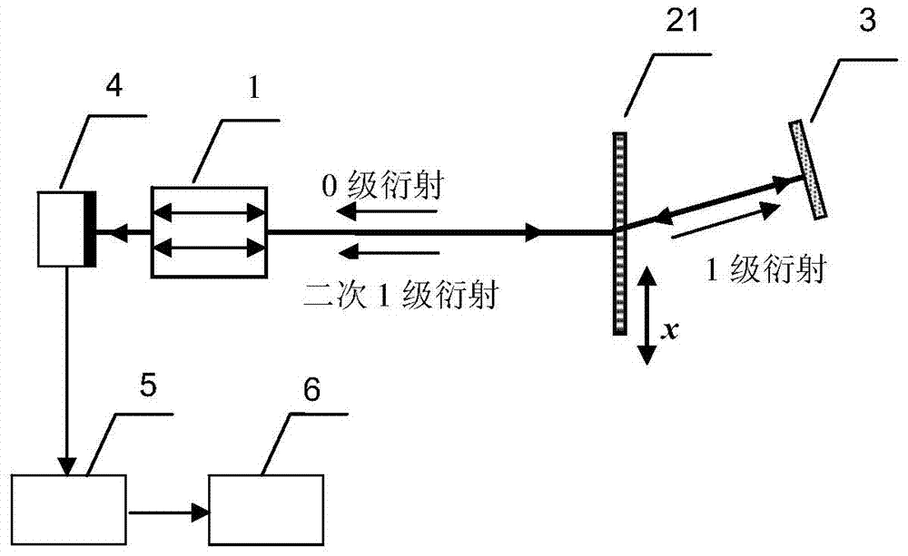
[0028] Such as figure 1 , The laser self-mixing grating interferometer in this embodiment includes: a laser 1, a transmission diffraction grating 21, a plane mirror 3, a photodetector 4, an electrical signal processing system 5, and a data acquisition and analysis system 6. The light output by the laser 1 is vertically incident on the transmissive diffraction grating 21 , and each level is symmetrically distributed on both sides of the incident light path. The plane reflector 3 is placed on the first-order diffraction optical path, and the plane reflector 3 is adjusted so that the first-order diffracted light beam is vertically incident on the plane reflector and returns along the original optical path, and then enters the diffraction grating 21 again, and secondary diffraction occurs. The first-order diffracted light returns to the cavity of the laser along the opposite direction of the output light of the laser 1, and self-mixes and interferes with the light in the cavity to...

Embodiment 2

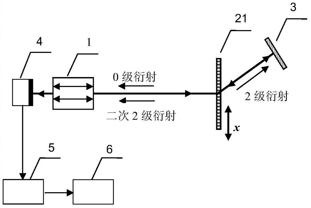
[0030] Such as image 3 , The laser self-mixing grating interferometer in this embodiment includes: a laser 1, a transmission diffraction grating 21, a plane mirror 3, a photodetector 4, an electrical signal processing system 5, and a data acquisition and analysis system 6. The light output by the laser 1 is vertically incident on the transmissive diffraction grating 21 , and each level is symmetrically distributed on both sides of the incident light path. The plane reflector 3 is placed on the second-order diffraction light path, and the plane reflector 3 is adjusted so that the second-order diffracted light is vertically incident on the plane reflector and returns along the original optical path, and then enters the diffraction grating 21 again, and secondary diffraction occurs. The second-order diffracted light returns to the cavity of the laser along the opposite direction of the output light of the laser 1, and self-mixes and interferes with the light in the cavity to mod...

Embodiment 3

[0032] Such as Figure 4 , The laser self-mixing grating interferometer in this embodiment includes: a laser 1, a reflective diffraction grating 22, a plane mirror 3, a photodetector 4, an electrical signal processing system 5, and a data acquisition and analysis system 6. The light output by the laser 1 is vertically incident on the reflective diffraction grating 21, and the 0th-order diffracted light returns to the resonator of the laser 1 along the original optical path, and the remaining levels are symmetrically distributed on both sides of the incident optical path. The plane reflector 3 is placed on the first-order diffraction optical path, and the plane reflector 3 is adjusted so that the first-order diffracted light is vertically incident on the plane reflector and returns along the original optical path, and then enters the diffraction grating 22 again, and secondary diffraction occurs. The first-order diffracted light returns to the cavity of the laser along the oppo...


PUM


Abstract

The invention discloses a laser self-blending grating interferometer and a measuring method thereof. The grating interferometer comprises a laser device, a diffraction grating, a plane mirror, a photoelectric detector, an electrical signal processing system and a data collecting and analyzing system. The diffraction grating is arranged on an output laser path of the laser device, and the displacement direction of the diffraction grating is perpendicular to the output laser path of the laser device. Laser emitted by the laser device is vertically incident to the diffraction grating to form all levels of diffraction laser symmetrically distributed at the two sides of an incident laser path, the plane mirror is arranged on a laser path of a certain m level of diffraction laser to enable the m (m is not equal to zero) level of diffraction laser to be vertically incident to the plane mirror, return along an original laser path and then be incident to the diffraction grating again for secondary diffraction, secondary diffraction laser carries grating displacement information to return into a cavity of the laser device in the direction opposite to emergent laser of the laser device for self-blending interference. The grating interferometer has the advantages of being simple and compact in structure, low in cost and high in capacity of resisting interference, and automatically recognizing the displacement direction, and the laser feedback level does not need to be controlled.

Description

technical field [0001] The invention belongs to the technical field of precision displacement measurement, and in particular relates to a laser self-mixing grating interferometer for measuring tiny displacements and a measurement method thereof. Background technique [0002] Laser interferometer is based on the method of optical interference, using the wavelength of light as the measuring ruler. It is an important tool for precision displacement measurement in the fields of science, engineering and industry. However, many interferometers on the market are complex and costly, and are large and expensive instruments. For example, the 5529A dual-frequency interferometer of Agilent Company of the United States. Laser self-mixing interference technology is a new type of interferometry technology with high application value that has emerged in recent years. This technology uses part of the laser light reflected or scattered by the measured object to recouple into the laser resonat...

Claims


Application Information

Patent Timeline
IPC IPC(8): G01B9/02G01B11/02
Inventor 郭冬梅王鸣郝辉夏巍倪小琦
Owner NANJING NORMAL UNIVERSITY
Why Eureka
Try Eureka