Laser self-mixing grating interferometer and its measuring method
A grating interference and self-mixing technology, which is applied in the direction of measuring devices, instruments, and optical devices, can solve the problems of complex structure and difficult adjustment of optical path, and achieve the effect of large measurement range, strong anti-interference and simple structure
- Summary
- Abstract
- Description
- Claims
- Application Information
AI Technical Summary
Problems solved by technology
Method used
Image
Examples
Embodiment 1
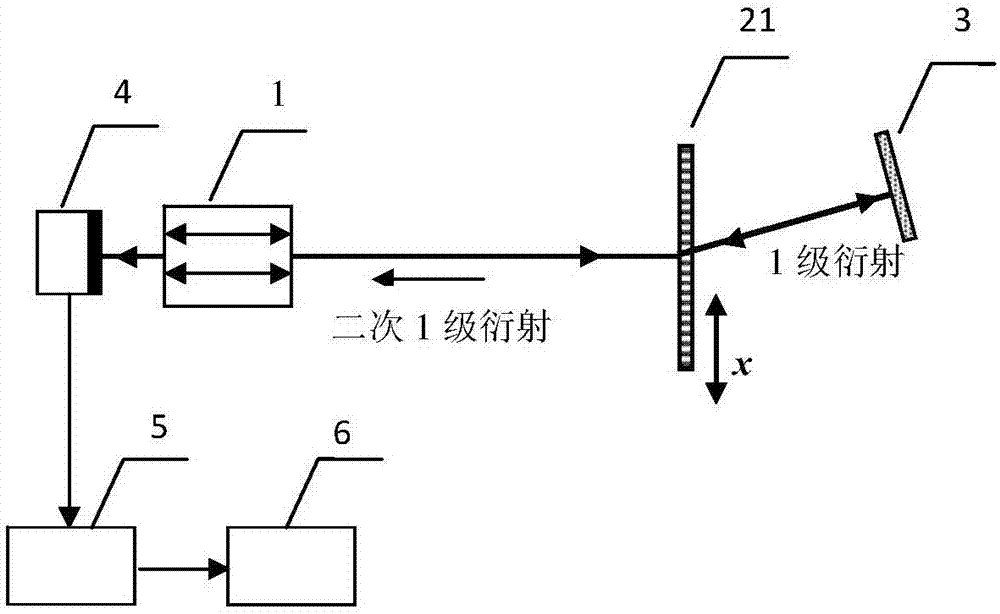
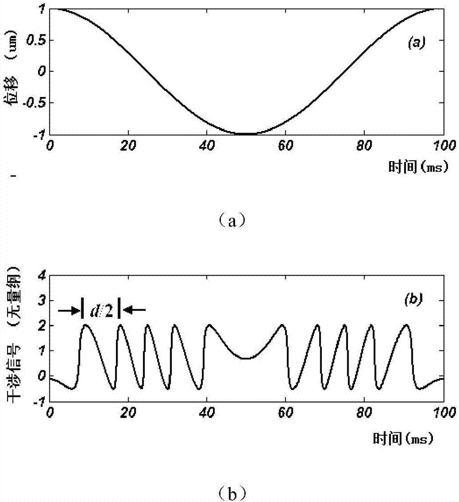
[0028] Such as figure 1 , The laser self-mixing grating interferometer in this embodiment includes: a laser 1, a transmission diffraction grating 21, a plane mirror 3, a photodetector 4, an electrical signal processing system 5, and a data acquisition and analysis system 6. The light output by the laser 1 is vertically incident on the transmissive diffraction grating 21 , and each level is symmetrically distributed on both sides of the incident light path. The plane reflector 3 is placed on the first-order diffraction optical path, and the plane reflector 3 is adjusted so that the first-order diffracted light beam is vertically incident on the plane reflector and returns along the original optical path, and then enters the diffraction grating 21 again, and secondary diffraction occurs. The first-order diffracted light returns to the cavity of the laser along the opposite direction of the output light of the laser 1, and self-mixes and interferes with the light in the cavity to...
Embodiment 2
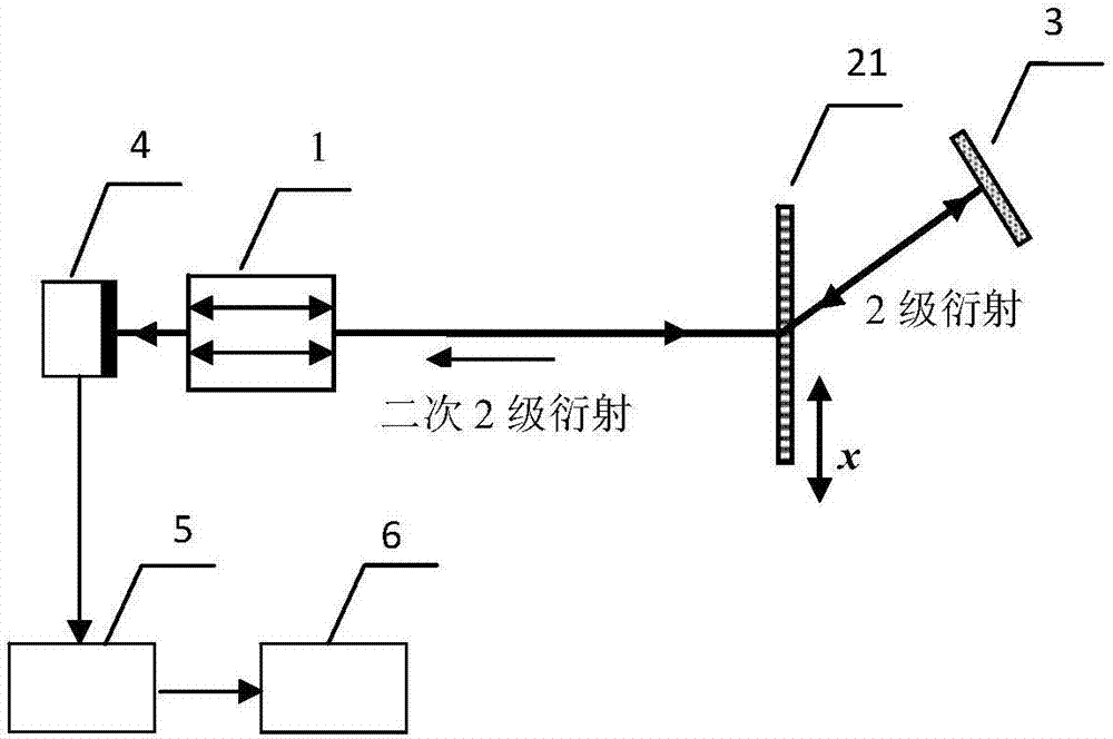
[0030] Such as image 3 , The laser self-mixing grating interferometer in this embodiment includes: a laser 1, a transmission diffraction grating 21, a plane mirror 3, a photodetector 4, an electrical signal processing system 5, and a data acquisition and analysis system 6. The light output by the laser 1 is vertically incident on the transmissive diffraction grating 21 , and each level is symmetrically distributed on both sides of the incident light path. The plane reflector 3 is placed on the second-order diffraction light path, and the plane reflector 3 is adjusted so that the second-order diffracted light is vertically incident on the plane reflector and returns along the original optical path, and then enters the diffraction grating 21 again, and secondary diffraction occurs. The second-order diffracted light returns to the cavity of the laser along the opposite direction of the output light of the laser 1, and self-mixes and interferes with the light in the cavity to mod...
Embodiment 3
[0032] Such as Figure 4 , The laser self-mixing grating interferometer in this embodiment includes: a laser 1, a reflective diffraction grating 22, a plane mirror 3, a photodetector 4, an electrical signal processing system 5, and a data acquisition and analysis system 6. The light output by the laser 1 is vertically incident on the reflective diffraction grating 21, and the 0th-order diffracted light returns to the resonator of the laser 1 along the original optical path, and the remaining levels are symmetrically distributed on both sides of the incident optical path. The plane reflector 3 is placed on the first-order diffraction optical path, and the plane reflector 3 is adjusted so that the first-order diffracted light is vertically incident on the plane reflector and returns along the original optical path, and then enters the diffraction grating 22 again, and secondary diffraction occurs. The first-order diffracted light returns to the cavity of the laser along the oppo...
PUM
 Abstract
Description
Claims
Application Information
 - R&D
- Intellectual Property
- Life Sciences
- Materials
- Tech Scout
- Unparalleled Data Quality
- Higher Quality Content
- 60% Fewer Hallucinations
Browse by: Latest US Patents, China's latest patents, Technical Efficacy Thesaurus, Application Domain, Technology Topic, Popular Technical Reports.
© 2025 PatSnap. All rights reserved.Legal|Privacy policy|Modern Slavery Act Transparency Statement|Sitemap|About US| Contact US: help@patsnap.com


