
Fault Diagnosis Method for Insufficient Coolant Flow in Electric Vehicle Cooling System

A technology for electric vehicles and cooling systems, used in hybrid) vehicles and electric (pure electric) fields, it can solve problems such as insufficient coolant flow, inability to identify and diagnose, and achieve the effect of reducing hardware costs

Active Publication Date: 2018-04-13
UNITED AUTOMOTIVE ELECTRONICS SYST
View PDF6 Cites 0 Cited by
  • Summary
  • Abstract
  • Description
  • Claims
  • Application Information

AI Technical Summary

Problems solved by technology

[0005] The cooling system used in electric vehicles usually does not install flow sensors to monitor the flow of coolant at any time due to cost issues, so it is impossible to identify and diagnose insufficient coolant flow due to various reasons

Method used


Image

  • Fault Diagnosis Method for Insufficient Coolant Flow in Electric Vehicle Cooling System
  • Fault Diagnosis Method for Insufficient Coolant Flow in Electric Vehicle Cooling System
  • Fault Diagnosis Method for Insufficient Coolant Flow in Electric Vehicle Cooling System

Examples


Embodiment 1

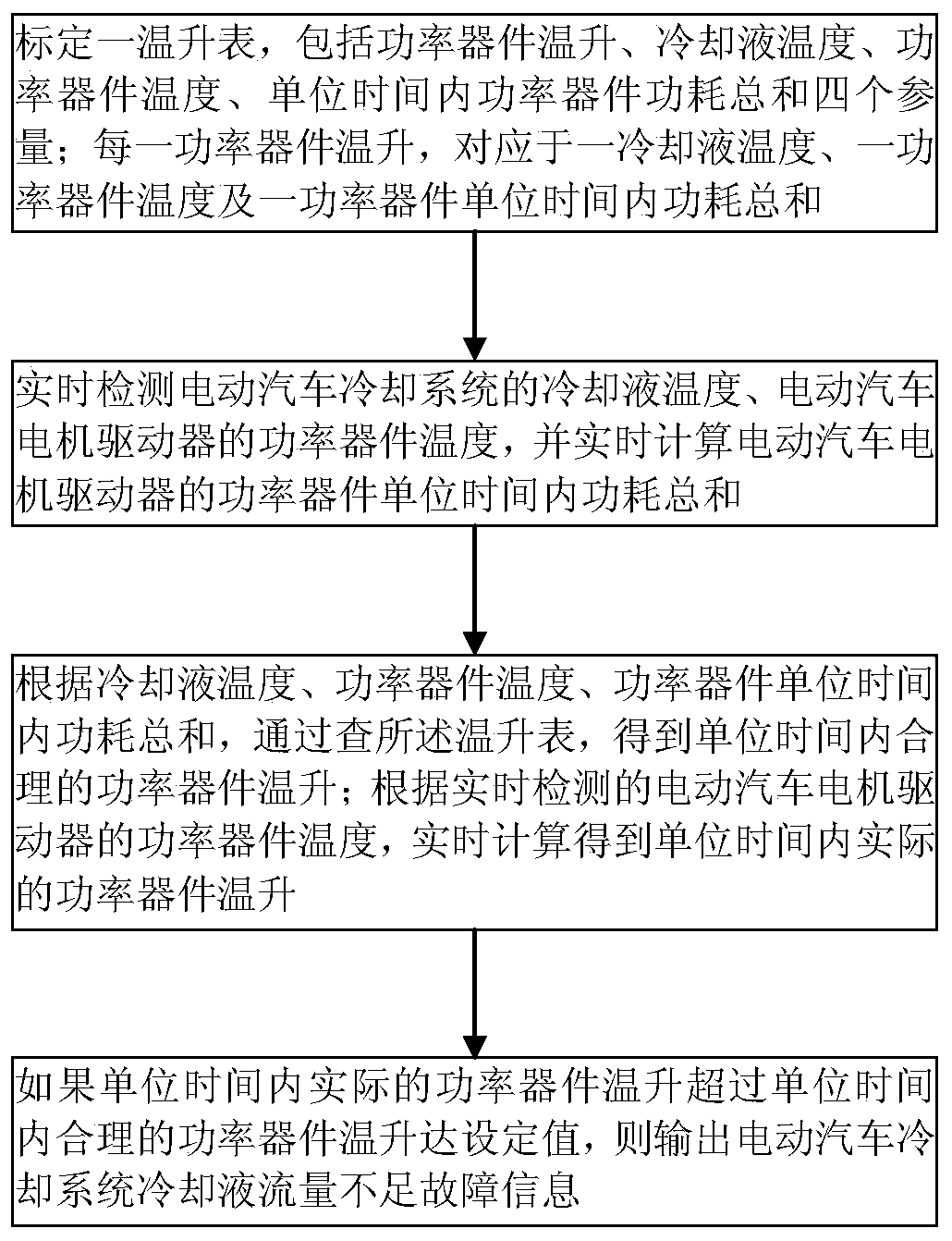
[0028] Fault diagnosis method for insufficient coolant flow in the cooling system of electric vehicles, such as figure 1 shown, including the following steps:

[0029] 1. Calibrate a temperature rise table, including four parameters of power device temperature rise, coolant temperature, power device temperature, and power device power consumption per unit time; each power device temperature rise corresponds to a coolant temperature and a power Device temperature and the sum of power consumption per unit time of a power device;

[0030] 2. Real-time detection of the coolant temperature of the electric vehicle cooling system and the temperature of the power device of the electric vehicle motor driver, and real-time calculation of the total power consumption of the power device of the electric vehicle motor driver per unit time;

[0031] 3. According to the coolant temperature obtained in step 2, the temperature of the power device, and the sum of the power consumption of the po...

Embodiment 2

[0040] Based on the method for diagnosing the failure of insufficient coolant flow in the cooling system of an electric vehicle in Embodiment 1, the calibration method of the temperature rise meter is as follows:

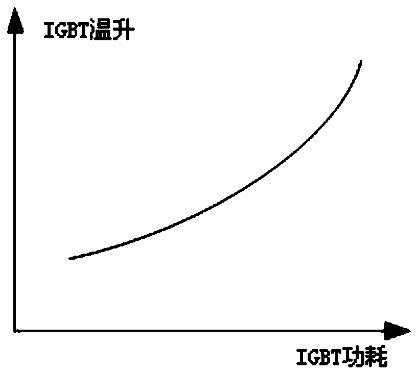
[0041] Keep the coolant temperature of the electric vehicle cooling system and the temperature of the power device of the electric vehicle motor driver unchanged, change the power consumption of the power device of the electric vehicle motor driver by changing the output torque of the electric vehicle motor, and measure the power device of the electric vehicle motor driver The sum of the power consumption per unit time reaches the temperature rise of the power device per unit time corresponding to N different expected power consumption values, and record the data to the corresponding position of the N*N*N temperature rise table;

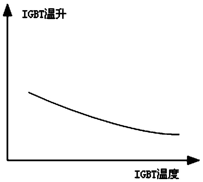
[0042] Keep the coolant temperature of the electric vehicle cooling system and the output torque of the electric vehicle motor constant, a...


PUM


Abstract

The invention discloses a fault diagnosis method for insufficient coolant flow in the cooling system of an electric vehicle, which is completed by calibrating a temperature rise meter, and the actual power device per unit time is calculated in real time according to the temperature of the power device of the electric vehicle motor driver detected in real time The temperature rise is compared with the reasonable power device temperature rise per unit time obtained by checking the temperature rise table based on the coolant temperature, power device temperature, and power device power consumption per unit time. If the actual power device temperature per unit time is calculated in real time If it rises too fast, it means that the coolant flow is insufficient. The method for diagnosing the insufficient coolant flow rate of the electric vehicle cooling system can use software to diagnose whether the current coolant flow rate is insufficient when the vehicle is not equipped with a flow sensor, thereby reducing hardware costs.

Description

technical field [0001] The invention relates to electric (pure electric, hybrid) vehicle technology, and in particular to a method for diagnosing a fault of insufficient coolant flow in a cooling system of an electric vehicle. Background technique [0002] The motor driver PEU of electric (pure electric, hybrid) vehicles will generate a lot of heat when it is working, and the heat can be dissipated by water cooling. However, when the coolant flow in the cooling system of the electric vehicle is insufficient, the temperature of the power device (such as IGBT, insulated gate bipolar transistor) of the motor driver will be too high, resulting in the overheating of the motor driver. [0003] A common method for over-temperature protection of the motor drive unit PEU is to limit the output torque when the temperature of the power device of the motor drive PEU exceeds a limit value, so as to achieve the protection function of the motor drive PEU. [0004] If you want to diagnose ...

Claims


Application Information

Patent Timeline
Patent Type & Authority Patents(China)
IPC IPC(8): G01F1/68
Inventor 赵阳高智
Owner UNITED AUTOMOTIVE ELECTRONICS SYST
Learn More