Nose humping method
A technique for rhinoplasty and nose, applied in the field of surgical plastic surgery, can solve the problems of difficult to guarantee the postoperative effect, difficult implementation, etc., and achieve the goal of reducing the difficulty and cost of the operation, reducing the postoperative risk, and improving the degree of fit. Effect
- Summary
- Abstract
- Description
- Claims
- Application Information
AI Technical Summary
Problems solved by technology
Method used
Image
Examples
Embodiment 1
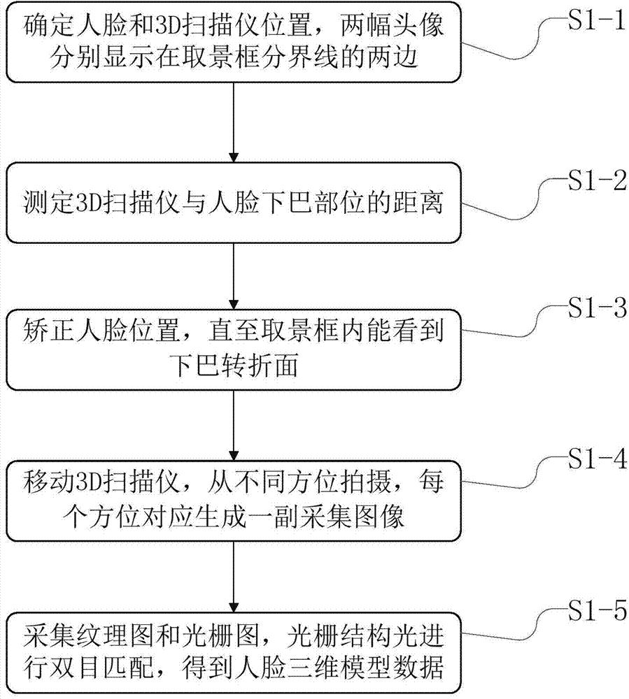
[0049] like figure 2 As shown, this embodiment discloses a method for collecting three-dimensional model data of a human face, that is, step S1 includes the following process:
[0050] S1-1, the face to be collected is positioned in the middle of the viewing range of the viewfinder of the 3D scanner, the face is divided into two head portraits, and the two head portraits are respectively displayed on both sides of the boundary line of the viewfinder frame;
[0051] S1-2, measuring the distance between the 3D scanner and the chin of the face;
[0052] S1-3. Correct the position of the face until the turning surface of the chin can be seen in the viewfinder;
[0053] S1-4. Move the 3D scanner, take photos from different directions, and generate a pair of captured images corresponding to each direction;
[0054] S1-5. Divide the acquired image into a texture image and a grating image, perform binocular matching according to the grating structured light, and finally complete 3D...
Embodiment 2
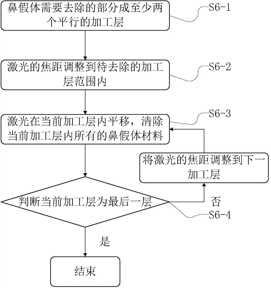
[0086] like image 3 As shown, this embodiment discloses a method for cutting the original nasal prosthesis with laser equipment, that is, step S6 includes the following process:
[0087] S6-1. Dividing the part of the nasal prosthesis to be removed into at least two parallel processing layers;
[0088] S6-2. Adjust the focal length of the laser to within the range of the processing layer to be removed;
[0089] S6-3. Keeping the focal length unchanged, the laser moves in the current processing layer until all nasal prosthesis materials in the current processing layer are removed;
[0090] S6-4. If the current processing layer is the last layer, end the step; otherwise, adjust the focal length of the laser to the next processing layer; return to step S3.
Embodiment 3
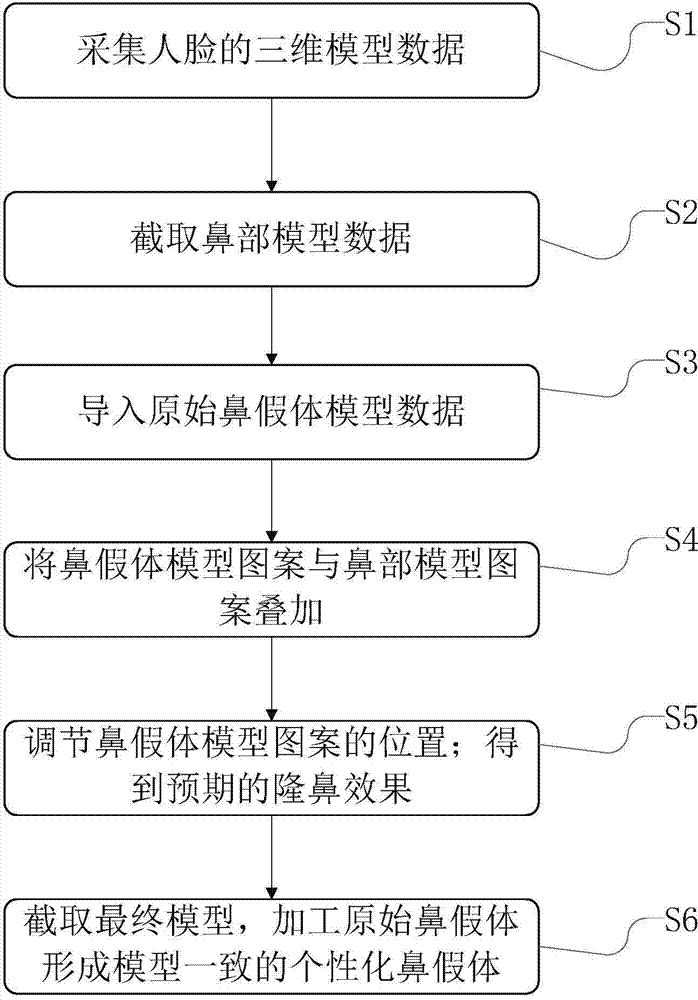
[0092] like Figure 4 As shown, the present embodiment discloses a method for rhinoplasty, which includes steps:
[0093] A method for rhinoplasty, including the steps of 3D modeling:
[0094] S1-1, the face to be collected is positioned in the middle of the viewing range of the viewfinder of the 3D scanner, the face is divided into two head portraits, and the two head portraits are respectively displayed on both sides of the boundary line of the viewfinder frame;
[0095] S1-2, measuring the distance between the 3D scanner and the chin of the face;
[0096] S1-3. Correct the position of the face until the turning surface of the chin can be seen in the viewfinder;
[0097] S1-4. Move the 3D scanner, take photos from different directions, and generate a pair of captured images corresponding to each direction;
[0098] S1-5. Divide the acquired image into a texture image and a grating image, perform binocular matching according to the grating structured light, and finally com...
PUM
| Property | Measurement | Unit |
|---|---|---|
| Thickness range | aaaaa | aaaaa |
Abstract
Description
Claims
Application Information
 - R&D
- Intellectual Property
- Life Sciences
- Materials
- Tech Scout
- Unparalleled Data Quality
- Higher Quality Content
- 60% Fewer Hallucinations
Browse by: Latest US Patents, China's latest patents, Technical Efficacy Thesaurus, Application Domain, Technology Topic, Popular Technical Reports.
© 2025 PatSnap. All rights reserved.Legal|Privacy policy|Modern Slavery Act Transparency Statement|Sitemap|About US| Contact US: help@patsnap.com


