Stirrer

A stirrer and air bubble technology, applied in chemical instruments and methods, chemical/physical/physical chemical fixed reactors, dissolution, etc., can solve problems such as unfavorable cleaning, low stirring efficiency, dead corner of stirring, etc., and achieve easy maintenance and cleaning , Improve stirring efficiency, eliminate the effect of stirring dead angle

Inactive Publication Date: 2015-06-24
薛应东
View PDF6 Cites 2 Cited by
  • Summary
  • Abstract
  • Description
  • Claims
  • Application Information

AI Technical Summary

Problems solved by technology

However, mechanical stirring, through the gear shifting of the motor through the gearbox, can reduce the speed of the stirring and then stir the materials in the reactor, but the motor consumes a lot of power, the speed change device needs maintenance, and the production cost is high.
Production also has the use of bubbling stirring. The bubbling stirring device of the prior art Chinese patent CN201887067U discloses a bubbling stirring type cashmere tank replenishment device, but its structure is complicated, and the bubbling form of the air outlet on the square tube is adopted. The gas flow can stir the materials in the reactor through the air outlet holes in the vertical and horizontal directions of the square tube. This kind of stirring device has shortcomings. The speed is also vertically upward. After the bubbles leave the air outlet, they quickly leave the reaction interface in the direction of the upward speed synthesized by the two speeds. The power consumption is large and the stirring efficiency is low; the second is easy to form a dead corner at the bottom of the reaction kettle; the third is multiple bubbling stirring parts. Placed at the bottom, and the structure is complex, easy to block, not conducive to cleaning
Chinese patent CN102078778A has a simple structure and is easy to clean and maintain, but there are also dead spots in the bottom of the reactor and the direction of the initial velocity is vertically upward, and the floating velocity of the bubbles is also vertically upward. Quickly break away from the reaction interface, the defects of low bubble stirring efficiency and large power consumption

Method used


Image

  • Stirrer
  • Stirrer

Examples


Embodiment

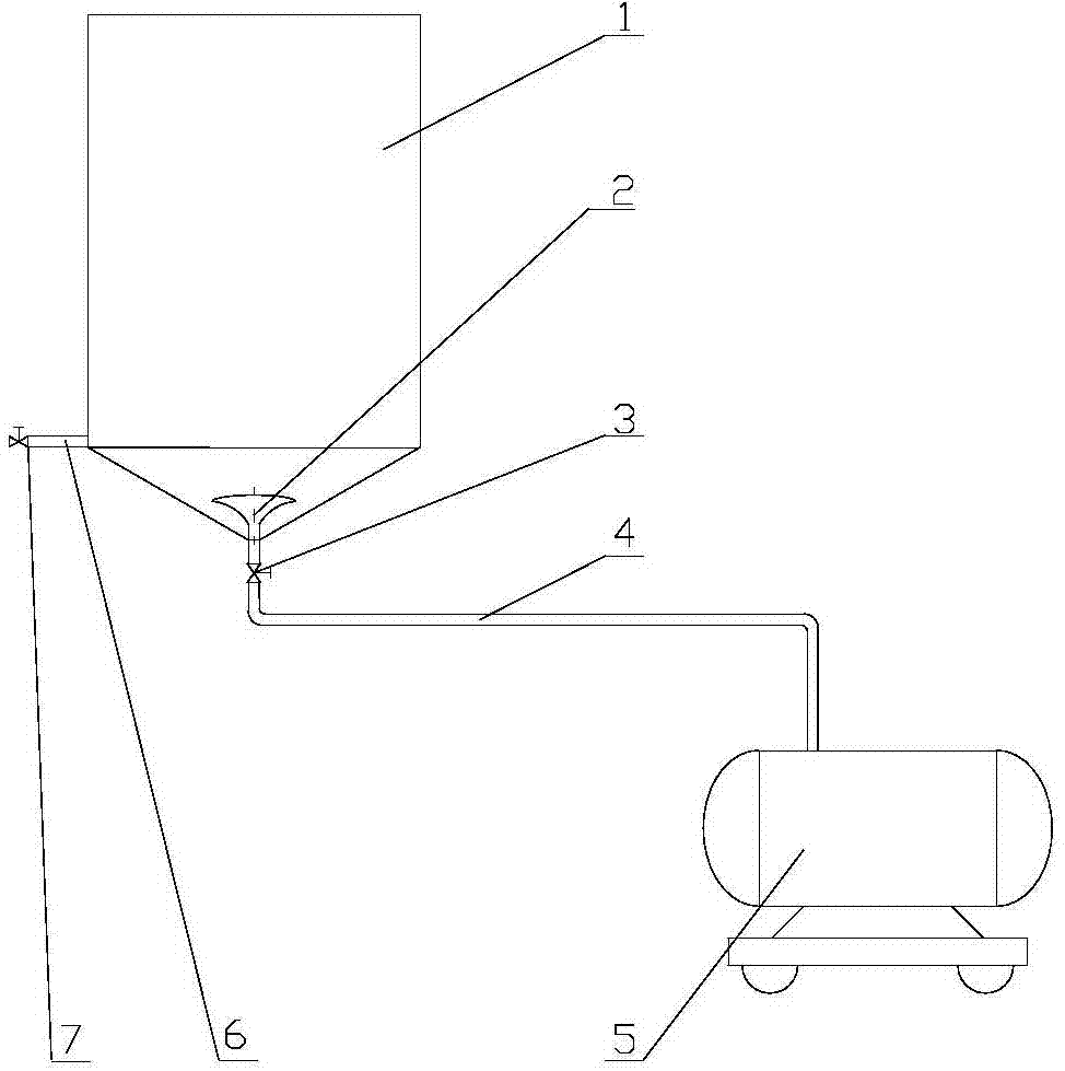
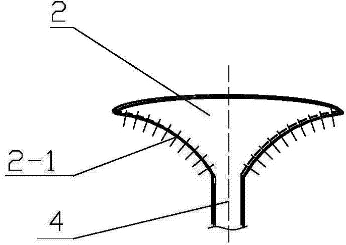
[0018] 1. A stirrer comprising a bubble stirrer 2, an overflow bubble hole 2-1, an air intake valve 3, an air intake pipe 4, and an air compressor 5, characterized in that: the bubble stirrer 2 is an inverted conical shape, and the bubble stirs Overflow foam hole 2-1 is arranged on the side of the cone of device 2, and bubble agitator 2 conical tops connect inlet pipe 4, and inlet valve 3 is housed on the inlet pipe 4, and inlet valve 3 connects air compressor 5.

[0019] 2. A stirrer, characterized in that: the conical side of the bubble stirrer 2 is an arc surface concave inward.

[0020] 3. A stirrer, characterized in that: the conical side of the bubble stirrer 2 is provided with a bubble overflow hole 2-1 with a diameter equal to 2-5mm.

[0021] 4. A stirrer, characterized in that: bubble overflow holes 2-1 are evenly distributed along the concave side of the cone.


PUM


Abstract

The invention provides a dead-angle-free stirring reactor and relates to the technical field of a reaction kettle. The stirrer comprises an air bubble stirrer, foam overflowing holes, an air inlet valve, an air inlet pipe and an air compressor, and is characterized in that the air bubble stirrer is in the shape of a reversed cone; the foam overflowing holes are formed in the side face of the cone of the air bubble stirrer; the top of the cone of the air bubble stirrer is connected with the air inlet pipe; the air inlet pipe is provided with the air inlet valve; and the air inlet valve is connected with the air compressor. The side face of the cone of the air bubble stirrer is an arc surface which is concave inwards. The foam overflowing holes with the equal pore diameter of 2mm-5mm are formed in the side face of the cone of the air bubble stirrer. The dead-angle-free stirring reactor has the characteristics of simple structure, convenience for installation, convenience for maintenance and low power consumption.

Description

[0001] A stirrer, which is a divisional application for the invention of "a stirred reactor without dead ends". Original application date: August 23, 2013, application number: 2013103711104, original invention name: a stirring reactor without dead ends. technical field [0002] A stirrer relates to the technical field of reactor stirrers. Background technique [0003] In chemical production, in order to fully mix and react the liquid-solid phase, the materials in the reactor are fully stirred and mixed in the form of spiral stirring, so that they can fully react. However, mechanical stirring, through the gear shifting of the motor through the gearbox, can reduce the speed of the stirring and then stir the materials in the reactor. However, the motor consumes a lot of power, the speed change device needs maintenance, and the production cost is high. Production also has the use of bubbling stirring. The bubbling stirring device of the prior art Chinese patent CN201887067U dis...

Claims


Application Information

Patent Timeline
Patent Type & Authority Applications(China)
IPC IPC(8): B01F13/02B01J19/24B01F33/40
Inventor 薛应东
Owner 薛应东
Why Eureka
Try Eureka