A kind of spiral pull-out type demoulding tool for composite material parts and its demoulding process

A technology for composite materials and parts, which is applied in the field of composite material manufacturing, can solve problems such as difficult removal of insert-type metal molds, and achieve the effects of avoiding tooling deformation and scrapping, reducing difficulty in demoulding, and improving pass rate and production efficiency

Active Publication Date: 2017-04-26
SHENYANG AIRCRAFT CORP
View PDF5 Cites 0 Cited by
  • Summary
  • Abstract
  • Description
  • Claims
  • Application Information

AI Technical Summary

Problems solved by technology

[0003] In view of the above deficiencies, the present invention provides a spiral pull-out type demoulding tool for composite material parts and its demoulding process, which solves the problem that it is difficult to take out the insert-type metal mold after the composite material part is solidified and formed, and ensures that the composite material part internal and external quality

Method used


Image

  • A kind of spiral pull-out type demoulding tool for composite material parts and its demoulding process
  • A kind of spiral pull-out type demoulding tool for composite material parts and its demoulding process
  • A kind of spiral pull-out type demoulding tool for composite material parts and its demoulding process

Examples


Embodiment 1

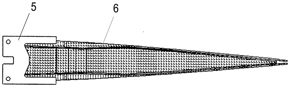
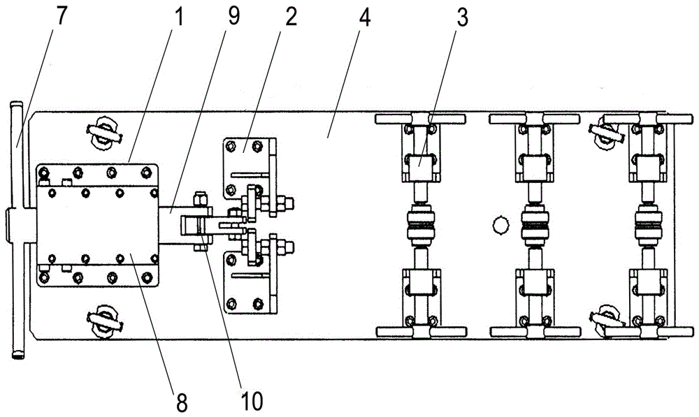
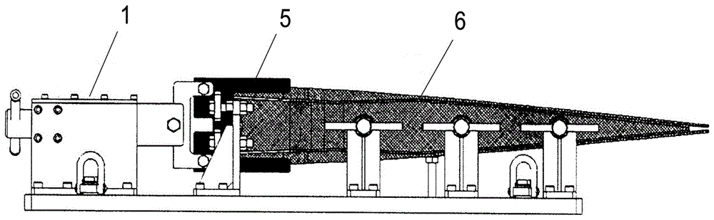
[0024] Such as figure 2 As shown, taking the I-shaped reinforcing rib in the rudder of a certain model as an example, the spiral pull-out type demoulding tooling used includes a screw pull-out assembly 1 for pulling the metal baffle 5, a screw pull-out assembly 1 for fixing the metal baffle 5 The positioning component 2 at the current position and the fixing component component 3 for fixing the composite material part 6 are three parts. The above-mentioned three part components are respectively fixed on the metal substrate 4 in sequence, and the distance between the components depends on the size of the composite material part. depends.

[0025] In the described spiral extraction assembly 1, the rotating handle 7 is fixedly connected with the screw rod in the metal box 8, the position of the screw rod relative to the metal box 8 is fixed, and the end of the screw rod is connected with the threaded stretching assembly 9, stretching The component 9 is connected with the metal ...

Embodiment 2

[0040] Continuing to take the I-shaped reinforcing rib in the rudder of a certain model as an example, the spiral pull-out type demoulding tooling used includes a screw pull-out assembly 1 for pulling the metal baffle 5, and a screw pull-out assembly 1 for fixing the current position of the metal baffle 5. The positioning assembly 2 and the fixing assembly 3 used to fix the composite material part 6 are three parts. The above three parts are respectively fixed on the metal substrate 4 in sequence, and the distance between the components is determined according to the size of the composite material part. .

[0041] In the screw extraction assembly 1, the hexagon socket nut is fixedly connected to the screw rod in the metal box 8, the position of the screw rod relative to the metal box 8 is fixed, and the end of the screw rod is connected to the threaded stretching assembly 9, stretching The component 9 is connected with the metal baffle 5 positioned on the positioning component...


PUM

PropertyMeasurementUnit
thicknessaaaaaaaaaa

Abstract

The invention provides a spiral pulling-out type demolding tool for composite products and a demolding process thereof. The demolding tool comprises a spiral pulling-out assembly, a positioning assembly and a fixed part assembly, wherein the spiral pulling-out assembly is used for drawing a metal baffle, the positioning assembly is used for fixing the current position of the metal baffle, and the fixed part assembly is used for fixing a composite product, and the three assemblies are sequentially respectively fixed on a metal substrate. According to the demolding process based on the demolding tool, a stable tensile force is provided by using a screw rotating device, a stable vertical pulling-out force is applied to the metal baffle in the product, and finally, the metal baffle clamped in the composite product is perfectly taken out.

Description

technical field [0001] The invention relates to a spiral pull-out type demoulding tool for composite material parts and a demoulding process thereof, belonging to the technical field of composite material manufacturing. Background technique [0002] Composite variable-section I-shaped parts belong to the main load-bearing structural parts, and are mainly used in aircraft rudders and wings. In order not to affect the overall mechanical properties of the part, metal baffles are usually used to reserve the assembly position of the composite part before curing and molding, such as figure 1 shown. Since the thermal expansion coefficient of the metal baffle is different from that of the composite material, there is internal stress after curing and forming, which makes it difficult to remove the metal baffle from the part after solidification. Faced with the above problems, those skilled in the art usually forcibly remove the metal baffle by knocking or other means, resulting in ...

Claims


Application Information

Patent Timeline
Patent Type & Authority Patents(China)
IPC IPC(8): B29C70/54B29C33/44B29L31/30
CPCB29C33/446B29C70/54B29L2031/3047B29L2031/3076B29L2031/3085
Inventor 张运湘王维蒲永伟张重阳关振庞城德
Owner SHENYANG AIRCRAFT CORP
Why Eureka
Try Eureka