

Production for conical cross winding column of S twisted yarn
A technology of cross-winding bobbins and twisting yarns, applied in the direction of thin material handling, conveying filamentous materials, transportation and packaging, etc., to avoid the effect of entanglement
- Summary
- Abstract
- Description
- Claims
- Application Information
AI Technical Summary
Problems solved by technology
Method used
Image

Examples
Embodiment Construction
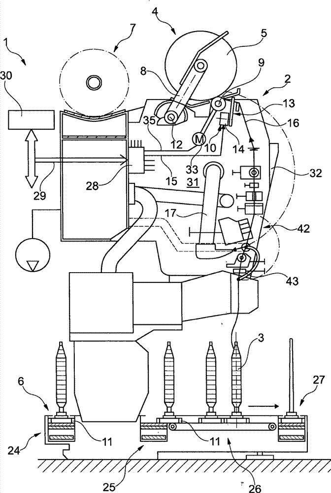
[0025] figure 1 A side view is schematically shown of a station 2 of a textile machine for producing cross-wound bobbins, in this embodiment a so-called automatic cross-winder 1 . Cops 3 having relatively little thread material and produced on ring spinning machines are rewound at station 2 of an automatic cross-winding winder 1 of this type to form bulky cross-wound bobbins 5 . Once the cross-wound bobbin 5 is formed, it is transferred to the cross-wound bobbin transfer mechanism 7 along the machine length by means of an automatically operated service assembly (not shown, preferably a cross-wound bobbin doffing machine) and transferred to the Package loading station at the end of the machine, etc.
[0026] Automatic cross-winding winders 1 of this type usually also have a logistics system in the form of a bobbin or tube delivery system 6 . Cops 3 or empty bobbins rotate on the delivery disc 11 of the bobbin or tube delivery system 6 . For bobbins or pipe delivery systems 6...
PUM
 Abstract
Description
Claims
Application Information