Axial flow compressor surge boundary measurement system

A technology of axial flow compressor and surge boundary, applied in the direction of mechanical equipment, machine/engine, liquid fuel engine, etc., can solve the problems of poor research and production value, dangerous equipment, poor visualization effect, etc., and achieve good research and The effects of production efficiency, uniform and regular operation interface, and convenient personnel monitoring

Inactive Publication Date: 2015-06-24
INST OF HIGH SPEED AERODYNAMICS OF CHINA AERODYNAMICS RES & DEV CENT
View PDF6 Cites 14 Cited by
  • Summary
  • Abstract
  • Description
  • Claims
  • Application Information

AI Technical Summary

Problems solved by technology

[0004] However, in the field of turbo compressor surge boundary measurement at this stage, especially in continuous high-speed wind tunnel applications, there is still no surge boundary measurement system that can be applied to the user's site
Even if the device or method can complete the determination of the surge boundary, there are still defects such as scattered equipment and operation interfaces, many post settings, and cumbersome procedures, which lead to high safety risks and poor measurement results; the universality of the surge determination device and criteria, The reliability is not strong, which brings great danger to the equipment in the wind tunnel circuit; it is impossible to s

Method used


Image

  • Axial flow compressor surge boundary measurement system
  • Axial flow compressor surge boundary measurement system
  • Axial flow compressor surge boundary measurement system

Examples


Embodiment Construction

[0034] All features disclosed in this specification, or steps in all methods or processes disclosed, may be combined in any manner, except for mutually exclusive features and / or steps.

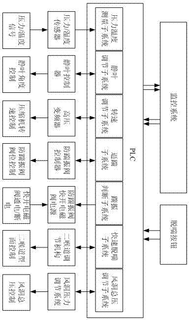
[0035] Such as figure 1Shown is a system functional block diagram of the present invention. Through two-way communication with the PLC control system, the upper monitoring interface realizes monitoring of the pressure measurement subsystem, stator blade adjustment subsystem, compressor speed adjustment subsystem, forced panting subsystem, surge judgment The voltage regulation subsystem involves the monitoring and control of the equipment. The upper monitoring interface and its background program record and display various parameters required by the surge boundary in real time.

[0036] Among them, the monitoring system and the PLC control system adopt the communication method based on the Ethernet TCP / IP protocol to realize the two-way transmission of data and control signals. The PLC contr...


PUM


Abstract

The invention discloses an axial flow compressor surge boundary measurement system. Aiming at an axial flow compressor installed in a wind tunnel major loop, by means of the system, the accurate measurement for a surge boundary of the axial flow compressor can be achieved, and it is sufficiently guaranteed that the surge boundary is applicable to future testing conditions of a wind tunnel, and the monitoring is facilitated. According to the method of the system, the measurement process is safe and reliable, and the surge boundary obtained through measurement is accurate; compared with domestic existing continuous type wind tunnel compressor surge boundary measurement methods, the method of the system is simpler, more accurate, safer and more reliable, and the result application is more convenient. The surge boundary measured by means of the axial flow compressor surge boundary measurement system is a smooth curve and conforms to performance characteristics of the axial flow compressor, the line type is simpler, the application is more convenient and faster, and the anti-surge program design and personnel monitoring are facilitated to a greater extent; the system particularly aims at new requirements for conducting measurement at different total pressure, at different stationary blade angles and under the condition to adjust the speed continuously within a total working revolving speed range.

Description

technical field [0001] The invention relates to the field of measuring the surge boundary of a turbo compressor, in particular to a system for measuring the surge boundary of an axial flow compressor installed in the main circuit of a continuous high-speed wind tunnel. Background technique [0002] Axial flow compressors in conventional industrial installations are mostly located in open pipe networks, and the speed, inlet flow, and inlet pressure of the compressors are relatively stable with little change, while the continuous wind tunnel is a special pipe network that is different from conventional industrial plants. The obvious characteristics of the environment: the wind tunnel and the axial flow compressor form a closed loop, the resistance of the pipe network changes frequently, the operating speed range of the compressor is large, the operating conditions are changeable, and individual operating points are close to the surge area, etc., so surge is more likely to occur...

Claims


Application Information

Patent Timeline
IPC IPC(8): F04D27/00F04D29/66
CPCF04D27/001
Inventor 周恩民刘恺张文李怀庆程松王仪田任国柱施宏博熊波许靖刘烽任栋庞旭东王小坤吴广
Owner INST OF HIGH SPEED AERODYNAMICS OF CHINA AERODYNAMICS RES & DEV CENT
Why Eureka
Try Eureka