Sealing mechanism preventing gas exchange

A technology of gas exchange and sealing mechanism, applied in the direction of engine sealing, mechanical equipment, engine components, etc., can solve problems such as explosion, safety hazards, damage, etc., and achieve the effect of simple operation and low cost

Active Publication Date: 2015-06-24
ZHE JIANG ECO ENVIRONMENTAL TECH CO LTD
View PDF9 Cites 24 Cited by
  • Summary
  • Abstract
  • Description
  • Claims
  • Application Information

AI Technical Summary

Problems solved by technology

figure 1 A schematic diagram showing the traditional body, such as figure 1 As shown, the furnace body 2 of the rotary carbonization furnace needs to be arranged on the body 1 with a rotatable gap, so there must be a gap at the connection between the furnace body 2 of the rotary carbonization furnace and the body 1 that fixes the rotary carbonization furnace, which will cause the rotation The gas in the furnace body 2 of the carbonization furnace will flow out from the gap between the furnace body 2 and the body 1, or the outside air will enter the furnace body 1 through the gap
[0003] In the actual use process, if gas exchange occurs at the connection between the furnace body 2 and the body 1 of the rotary carbonization furnace, that is, the external air enters the rotary carbonization furnace from this connection, the oxygen-deficient environment in the carbonization furnace may be destroyed , affecting the pyrolysis and carbonization process of sludge. At the same time, due to the entry of air, the flammable active gas in the pyrolysis gas may explode under the action of oxygen, and there are certain safety hazards.

Method used


Image

  • Sealing mechanism preventing gas exchange
  • Sealing mechanism preventing gas exchange
  • Sealing mechanism preventing gas exchange

Examples


Embodiment 1

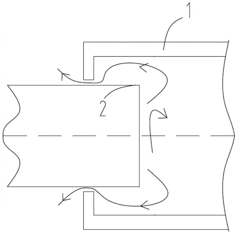
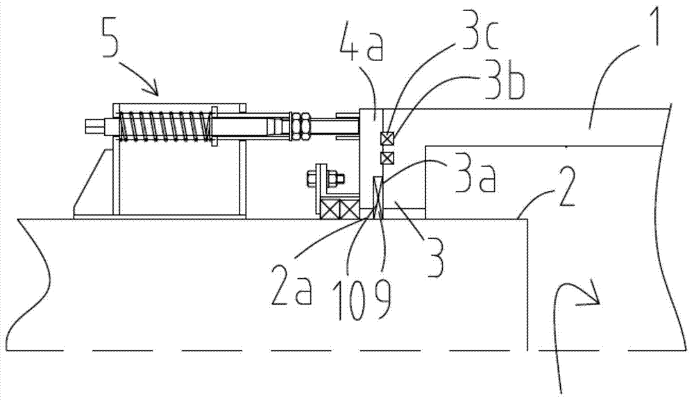
[0033] figure 1 Schematic diagram showing the structure of the rotating part and the fixed part; figure 2 For the structural representation of embodiment one of the sealing mechanism of anti-gas exchange; figure 2 As shown, a sealing mechanism for preventing gas exchange includes a receiving block 3 that is connected with the fixed part 1 and has a clearance fit with the rotating part 2, a pressure block 4 that is rotationally fitted with the rotating part 2 and is fixedly connected with the rotating part 2. The pressing mechanism 5, the pressing block 4 is tested to the receiving block 3 through the pressing mechanism 5; the receiving block 3 has a first plane 3a for pressing, and the first plane 3a is provided with two annular grooves 3b, the annular A first sealing strip 3c is arranged in the groove 3b;

[0034] image 3 It is a schematic structural view of the briquetting block in the sealing mechanism for preventing gas exchange according to Embodiment 1; as image ...

Embodiment 2

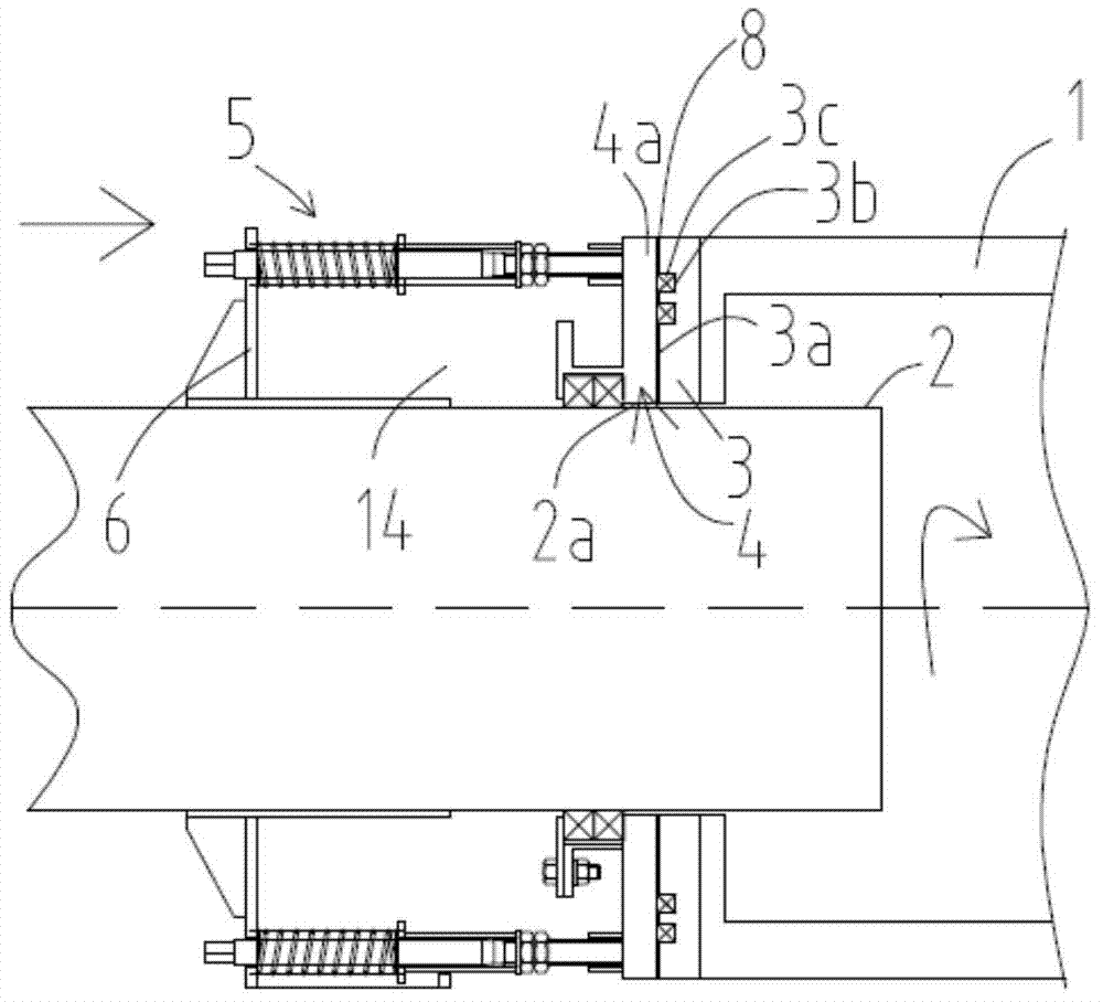
[0038] Image 6 Schematic diagram of the second embodiment of the sealing mechanism for preventing gas exchange. Image 6 It is a schematic structural diagram of Embodiment 2 of the flue gas treatment system. like figure 2 As shown, the pressing surface 4a1 of the present invention also includes a second surface 4a3, the second surface 4a3 is laterally away from the first pressing surface 4a2, and the second surface 4a2 and the first surface 3a of the receiving block 3 and the outer wall of the rotating member 2 form a second surface. A channel 9 also includes a second fixing plate 14 , which is fixed on the outer wall of the rotating member 2 and arranged flush with the first fixing plate 6 , and the screw rod 7a passes through the second fixing plate 14 .

[0039] It should be noted that, except for this, other structures of this embodiment may be the same as those of Embodiment 1, which need not be repeated here.

Embodiment 3

[0041] Figure 7 Schematic diagram of the third embodiment of the sealing mechanism for preventing gas exchange. like Figure 7 As shown, the first baffle 11 and the second baffle 12 are staggered in the first channel 9 of the present invention to form an "S" shaped channel. Insulation cotton 13 is arranged in the "S" shaped channel. It should be noted that, except for this, other structures of this embodiment may be the same as those of Embodiment 1, which need not be repeated here.


PUM


Abstract

The invention relates to a sealing mechanism preventing gas exchange. The sealing mechanism comprises a stress block (3), a pressing block (4) and a compressing mechanism (5), wherein the stress block (3) is connected with a fixed part (1) and is in clearance fit with a rotating part (2); the pressing block (4) is in clearance fit with the rotating part (2) in a rotating mode; the compressing mechanism (5) is fixedly connected with the rotating part (2); the pressing block (4) presses the stress block (3) through the compressing mechanism; the stress block (3) is provided with a first sealing strip (3c); a second sealing strip (4e) is placed in a cavity (4d) of the pressing block (4); a first gap (2a) formed between the pressing block (4) and the outer wall surface of the rotating part (4) is sealed through the second sealing strip (4e); a threaded rod (7a) of a compressing screw (7) of the compressing mechanism (5) applies pressure to a force applying surface (4a2) of the pressing block (4), and the pressing block (4) compresses the first sealing strip (3c) of the stress block (3) through a first pressing surface (4a2) of a compressing surface (4a1) so that a second gap (8) formed between the pressing block (4) and the stress block (3) can be sealed. The sealing function is achieved through the simple mechanical sealing mechanism, gas exchange through the gap formed between the fixed part and the rotating part is prevented, in this way, external gas is prevented from entering the rotating part through the gap, and meanwhile gas inside the rotating part is prevented from leaking outwards through the gap.

Description

technical field [0001] The invention relates to a sealing mechanism for preventing gas exchange, in particular to a sealing mechanism for preventing gas from being exchanged through the gap formed between the body and the rotating body. The invention also relates to a rotary machine having such a sealing mechanism; more particularly, to a rotary furnace having such a sealing mechanism. Background technique [0002] The invention of the application number 201320497216.4 published on January 29, 2014 discloses a device for carbonization treatment and carbon recovery of oil refinery sludge. The front unit is an external heat dryer, and the dryer is equipped with a dryer jacket. (2); the carbonization unit is an externally heated rotary carbonization furnace (3), and the rotary carbonization furnace (3) is provided with a rotary carbonization furnace jacket (4). Refinery sludge is pyrolytically carbonized in a rotary carbonization furnace, which needs to maintain an oxygen-defi...

Claims


Application Information

Patent Timeline
Patent Type & Authority Applications(China)
IPC IPC(8): F16J15/16F16J15/06C02F11/10
CPCC02F11/10F16J15/06F16J15/16
Inventor 车磊
Owner ZHE JIANG ECO ENVIRONMENTAL TECH CO LTD
Why Eureka
Try Eureka