RF impedance model based fault detection

A technology of models and faults, applied in the direction of measuring electricity, measuring devices, measuring electrical variables, etc.

Active Publication Date: 2015-06-24
LAM RES CORP
View PDF9 Cites 0 Cited by
  • Summary
  • Abstract
  • Description
  • Claims
  • Application Information

AI Technical Summary

Problems solved by technology

Several examples are described below

Method used


Image

  • RF impedance model based fault detection
  • RF impedance model based fault detection
  • RF impedance model based fault detection

Examples


Embodiment Construction

[0027]The following embodiments describe systems and methods for fault detection based on radio frequency (RF) impedance models. Obviously, the present embodiments may be practiced without some or all of these specific details. In other instances, well known process operations have not been described in detail in order not to unnecessarily obscure the present embodiments.

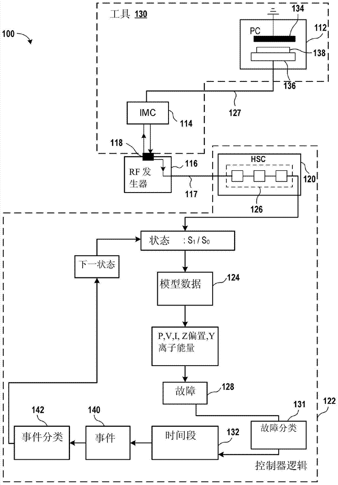
[0028] Figure 1A is a block diagram of an embodiment of a plasma system 100 for RF impedance model based fault detection. Plasma system 100 includes plasma chamber 112 , impedance matching circuit 114 , one or more RF generators 116 , and host system 120 for generating model data 124 . In some embodiments, model data 124 includes variable values ​​such as complex voltage and current, impedance, complex forward power, complex reflected power, complex transmitted power, and the like. In some embodiments, the complex voltage and current include a voltage magnitude V, a current magnitude I, and a phase φ bet...


PUM


Abstract

The present invention relates to RF impedance model based fault detection. A method for detecting latent fault in a plasma system is described. The method comprises accessing models of one or more parts of the plasma system. The method also comprises receiving data relative to providing RF power to a plasma cavity. The RF power is provided by using arrangement comprising one or more status. The method also comprises using the data to generate model data at the model output portion. The method comprises inspecting the model data. The inspection relates to inspecting one or more variables representing performance of the plasma process of the plasma system. The method comprises identifying the faults of the one or more variables. The method also comprises determining a predetermined time period of fault appearance so as to identify the faults as incidents. The method comprises classifying the incidents.

Description

technical field [0001] The present embodiments relate to systems and methods for fault detection based on radio frequency (RF) impedance models. Background technique [0002] In a plasma system, a signal source generates a radio frequency (RF) signal to provide to a plasma chamber. When a signal is received by the plasma chamber, gas within the plasma chamber is ignited to generate a plasma within the plasma chamber. [0003] Plasmas are used for many operations on substrates, such as cleaning substrates, processing substrates, depositing oxides on substrates, etching substrates, and the like. During operation, various impedances are encountered. For example, plasma unconfinement may exist within a plasma chamber. As another example, there may be arcing or plasma loss. These events reduce wafer throughput and increase the time and cost associated with performing operations. [0004] It is against this background that the embodiments described in this disclosure have bee...

Claims


Application Information

Patent Timeline
Patent Type & Authority Applications(China)
IPC IPC(8): G01R31/00
CPCG01R31/00H05H1/46G01R31/001
Inventor 约翰·C·小瓦尔考詹姆斯·休·罗杰斯尼古拉斯·爱德华·韦布彼得·T·穆拉卡
Owner LAM RES CORP
Why Eureka
Try Eureka