Laminated sheet type magnetic bead

A chip and magnetic bead technology, applied in the direction of magnetic core/yoke, electrical component structure association, electrical components, etc., can solve the problem of limited layout of printed circuit boards, save wiring space and reduce occupied space Effect

Active Publication Date: 2015-06-24
KUSN INFOVISION OPTOELECTRONICS
View PDF5 Cites 5 Cited by
  • Summary
  • Abstract
  • Description
  • Claims
  • Application Information

AI Technical Summary

Problems solved by technology

However, in the actual printed circuit board layout (PCB layout), since most fuses and magnetic beads are packaged i

Method used


Image

  • Laminated sheet type magnetic bead
  • Laminated sheet type magnetic bead
  • Laminated sheet type magnetic bead

Examples


Embodiment Construction

[0018] In order to further illustrate the technical means and effects adopted by the present invention to achieve the predetermined purpose of the invention, the specific embodiments, structures, features and effects of the present invention are described in detail below with reference to the accompanying drawings and preferred embodiments.

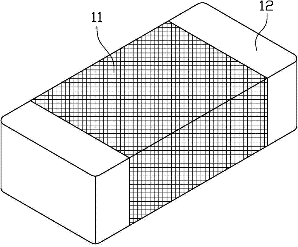
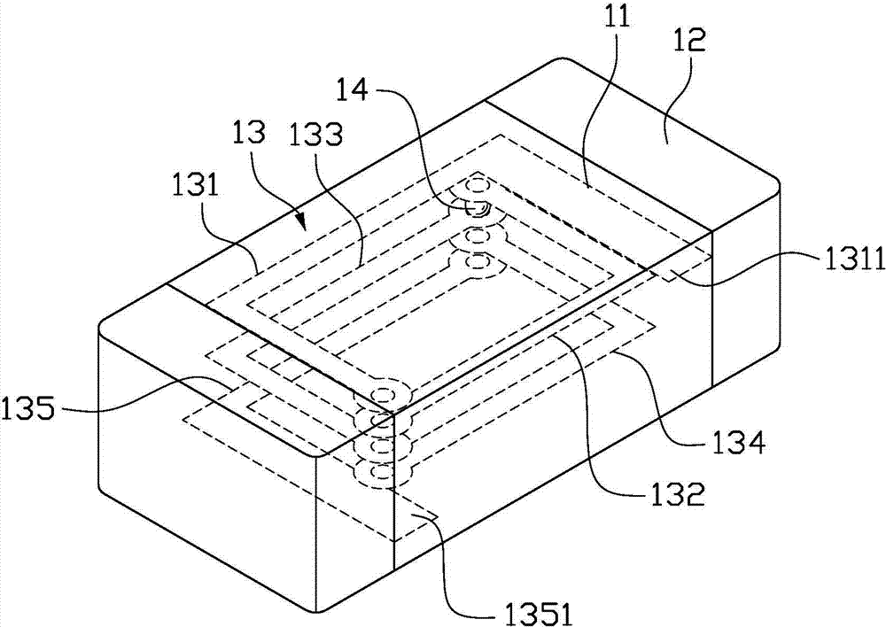
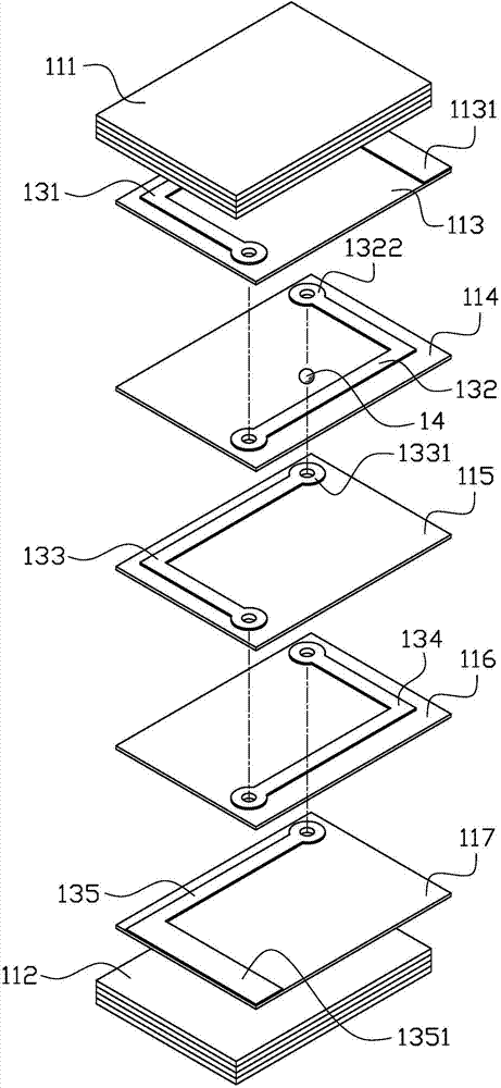
[0019] figure 1 It is a schematic diagram of the external structure of the laminated chip magnetic bead in one embodiment of the present invention. figure 2 It is a perspective schematic diagram of a laminated chip magnetic bead in an embodiment of the present invention. please combine figure 1 and figure 2 , the laminated chip magnetic bead of the present invention includes a laminated body 11, a terminal electrode 12 and an inner electrode coil 13, the inner electrode coil 13 is located inside the laminated body 11, the terminal electrodes 12 are located on both sides of the laminated body 11, and the inner electrode coil 13 is loca...


PUM


Abstract

The invention provides a laminated sheet type magnetic bead. The laminated sheet type magnetic bead comprises a laminated body, end electrodes and an inner electrode coil. The end electrodes are located on the two sides of the laminated body and connected with the two ends of the inner electrode coil respectively. The laminated body comprises multiple layers of base body membranes, the inner electrode coil is formed by sequentially connecting inner electrode units located between different layers of base body membranes, each inner electrode unit is provided with a leading-out end and a leading-in end, the leading-out ends and the leading-in ends of every two adjacent inner electrode units of the inner electrode coil are connected through fuse metal connecting pieces, when the temperature of the inner electrode coil is higher than that of the fusion points of the fuse metal connecting pieces, the fuse metal connecting pieces are fused, and the inner electrode coil is disconnected. The fuse metal connecting pieces are adopted for connecting every two adjacent inner electrode units, so that the laminated sheet type magnetic bead has the magnetic bead function and the fuse function at the same time.

Description

technical field [0001] The present invention relates to the technical field of electronic components, in particular to a laminated chip magnetic bead. Background technique [0002] In circuit design, the external power supply is generally provided by the system. Since the external power supply provided by the system will have a certain noise (Noisy), the noise will enter the Printed Circuit Board (PCB) and affect EMI (Electromagnetic Interference, Electromagnetic Interference). ), RF (Radio Frequency, radio frequency) test results, so it is necessary to place a magnetic bead (Bead) component at the power input end to suppress high-frequency noise and spike interference on signal lines and power lines, and play a filtering role. In addition, due to the instability of the external power supply provided by the system, such as high current and high voltage, in order to protect the components in the circuit from being burned and seriously affected when large current and high volt...

Claims


Application Information

Patent Timeline
IPC IPC(8): H01F17/00H01F3/00H01F27/28H01F27/40
Inventor 双强吴春芸杨天宇
Owner KUSN INFOVISION OPTOELECTRONICS
Why Eureka
Try Eureka