A Bandpass Filter Based on Gap Waveguide Technology

A band-pass filter and gap waveguide technology, applied in the field of electronics, can solve the problems of long processing cycle, unfavorable batch production, high product cost, etc., and achieve the effect of easy batch production, simple design, and easy processing

Inactive Publication Date: 2017-09-15
XIDIAN UNIV
View PDF5 Cites 0 Cited by
  • Summary
  • Abstract
  • Description
  • Claims
  • Application Information

AI Technical Summary

Problems solved by technology

However, the realization of these conditions will lead to high product cost and long processing cycle, which is not conducive to mass production

Method used


Image

  • A Bandpass Filter Based on Gap Waveguide Technology
  • A Bandpass Filter Based on Gap Waveguide Technology
  • A Bandpass Filter Based on Gap Waveguide Technology

Examples


Embodiment Construction

[0024] The present invention will be described in further detail below in conjunction with the accompanying drawings.

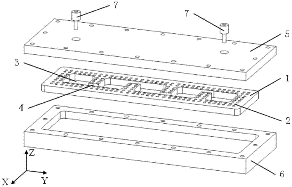
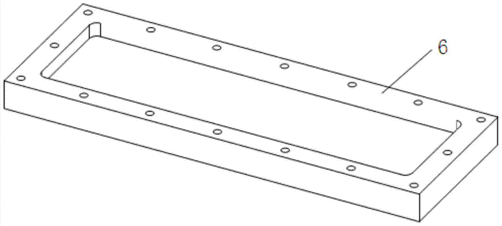
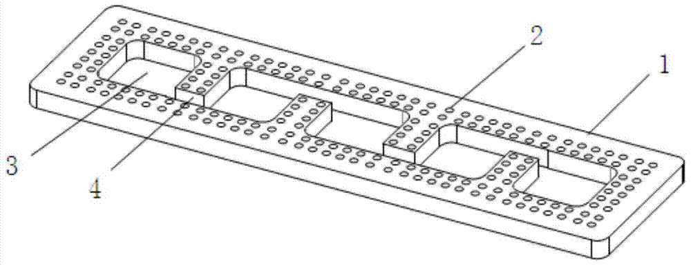
[0025] see figure 1 , 2, 3, 4, the bandpass filter based on microstrip slot-gap waveguide technology of the present invention mainly includes the following four parts: dielectric substrate 1, metal cover plate 5, metal floor 6 and feeding probe 7. A part of the dielectric substrate 1 is milled off, and the unmilled part is distributed with periodically arranged metallized via holes 2, and the lower surface of the unmilled part of the dielectric substrate 1 is covered with metal; the metal cover plate 5 is placed on the dielectric substrate 1 Above the surface, there is a gap between the metal cover plate 5 and the metallized via hole 2 on the dielectric substrate 1; the metal floor 6 is placed under the lower surface of the dielectric substrate 1, and the metal floor 6 is electrically connected to the metal part of the lower surface of the dielectric substrat...


PUM


Abstract

A bandpass filter based on gap waveguide technology, including a metal floor with grooves on the surface, and a metal cover plate that cooperates with the metal floor to form a closed cavity; a dielectric substrate is arranged in the closed cavity, and the dielectric substrate has periodic interlaced The arranged coupling structure and the tank separated by the coupling structure are used to combine the metal cover plate and the metal floor to form a resonant cavity; the metal cover plate has a through hole for installing the feeding probe, the dielectric substrate and the metal cover There is a gap between the boards and between the dielectric substrate and the feeding probe, and the electrical connection between the dielectric substrate and the metal floor and between the metal floor and the metal cover; the surface of the dielectric substrate is distributed with metallized via holes arranged periodically. Through the metallized via holes, the metal cover plate and the metal floor form a periodic electromagnetic bandgap structure of a bandpass filter, and electromagnetic waves are only transmitted on the slot gap of the dielectric substrate. The invention has strong out-of-band suppression performance, obvious filtering effect, easy processing and is suitable for mass production.

Description

technical field [0001] The invention belongs to the field of electronic technology, and in particular relates to a band-pass filter based on gap waveguide technology. Background technique [0002] Gap waveguides are classified into ridge-gap waveguides and groove-gap waveguides. As a new type of transmission structure, the ridge-gap waveguide was first proposed in 2009. Its structure is formed by arranging electromagnetic bandgap around the metal ridge on the surface of a flat plate of the parallel plate waveguide. When the distance between the upper metal plate and the electromagnetic bandgap surface is less than At a quarter wavelength, due to the bandgap characteristics of the electromagnetic bandgap structure, the electromagnetic wave cannot propagate in it, but only propagates in the quasi-TEM mode in the direction of the metal ridge, and cuts off other modes in a wide frequency band, thus Hence the name ridge-gap waveguide. Later, the slot-gap waveguide was developed...

Claims


Application Information

Patent Timeline
Patent Type & Authority Patents(China)
IPC IPC(8): H01P1/208
Inventor 樊芳芳吕苗王金辉鄢泽洪张天龄
Owner XIDIAN UNIV
Why Eureka
Try Eureka