SCR (Selective Catalytic Reduction) flue gas denitration device and flue gas denitration method

A technology for flue gas and denitrification, applied in separation methods, chemical instruments and methods, and separation of dispersed particles, can solve problems affecting the mixing distance of ammonia injection grids and denitrification efficiency, increase flue gas resistance, and poor injection rigidity, etc., to achieve Improve the mixing effect and denitrification efficiency, reduce the smoke resistance, and reduce the effect of mixing distance

Inactive Publication Date: 2015-07-01
CHINA HUADIAN ENG +1
View PDF3 Cites 12 Cited by
  • Summary
  • Abstract
  • Description
  • Claims
  • Application Information

AI Technical Summary

Problems solved by technology

so to NH 3 The mixing with the flue gas has a certain promoting effect, but due to the high speed of the flue gas here, the resistance of the flue gas is also greatly increased
In addition, the ammonia injection grid with holes on the metal tube bundle is used. Due to the poor injection rigidity of the small holes, the mixing effect of the injected ammonia and flue gas is poor, which affects the mixing distance and denitrification efficiency of the ammonia injection grid.

Method used


Image

  • SCR (Selective Catalytic Reduction) flue gas denitration device and flue gas denitration method
  • SCR (Selective Catalytic Reduction) flue gas denitration device and flue gas denitration method
  • SCR (Selective Catalytic Reduction) flue gas denitration device and flue gas denitration method

Examples


Embodiment 1

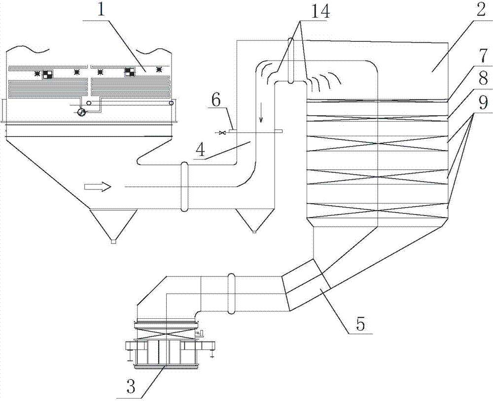
[0033] Embodiment 1 of the present invention: as figure 1 As shown, an SCR flue gas denitration device includes an economizer 1, a denitration reactor 2 and an air preheater 3. The bottom of the economizer 1 is connected to the top of the denitration reactor 2 through an inlet flue 4, and the denitration reaction The bottom of the device 2 is connected to the air preheater 3 through the outlet flue 5, the ammonia injection device 6 is installed in the inlet flue 4, and the ash crushing device 7, the rectifying layer 8 and the catalyst are installed in the denitrification reactor 2 from top to bottom. Layer 9.

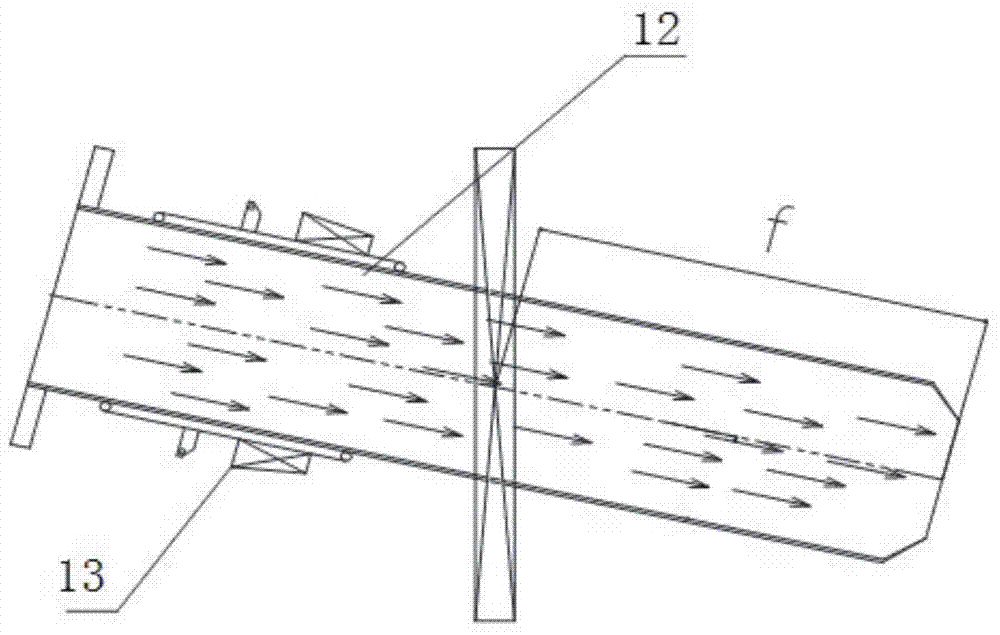
[0034] Such as figure 2 As shown, the ammonia injection device 6 includes a nozzle 12 and an angle adjustment baffle 13, the angle adjustment baffle 13 is installed on the nozzle 12, and the angle between the opening direction of the nozzle 12 and the flue gas flow direction is -60°~+60° °, the length f of the nozzle 12 deep into the inlet flue 4 is 0mm.

[0035] Su...

Embodiment 2

[0046] Embodiment 2 of the present invention: as figure 1As shown, an SCR flue gas denitration device includes an economizer 1, a denitration reactor 2 and an air preheater 3. The bottom of the economizer 1 is connected to the top of the denitration reactor 2 through an inlet flue 4, and the denitration reaction The bottom of the device 2 is connected to the air preheater 3 through the outlet flue 5, the ammonia injection device 6 is installed in the inlet flue 4, and the ash crushing device 7, the rectifying layer 8 and the catalyst are installed in the denitrification reactor 2 from top to bottom. Layer 9.

[0047] Such as figure 2 As shown, the ammonia injection device 6 includes a nozzle 12 and an angle adjustment baffle 13, the angle adjustment baffle 13 is installed on the nozzle 12, and the angle between the opening direction of the nozzle 12 and the flue gas flow direction is -60°~+60° °, the length f of the nozzle 12 deep into the inlet flue 4 is 250mm.

[0048] S...

Embodiment 3

[0059] Embodiment 3 of the present invention: as figure 1 As shown, an SCR flue gas denitration device includes an economizer 1, a denitration reactor 2 and an air preheater 3. The bottom of the economizer 1 is connected to the top of the denitration reactor 2 through an inlet flue 4, and the denitration reaction The bottom of the device 2 is connected to the air preheater 3 through the outlet flue 5, the ammonia injection device 6 is installed in the inlet flue 4, and the ash crushing device 7, the rectifying layer 8 and the catalyst are installed in the denitrification reactor 2 from top to bottom. Layer 9.

[0060] Such as figure 2 As shown, the ammonia injection device 6 includes a nozzle 12 and an angle adjustment baffle 13, the angle adjustment baffle 13 is installed on the nozzle 12, and the angle between the opening direction of the nozzle 12 and the flue gas flow direction is -60°~+60° °, the length f of the nozzle 12 deep into the inlet flue 4 is 500mm.

[0061] ...


PUM


Abstract

The invention discloses an SCR (Selective Catalytic Reduction) flue gas denitration device and a flue gas denitration method. The SCR flue gas denitration device comprises a coal economizer (1), a denitration reactor (2) and an air preheater (3), wherein the bottom of the coal economizer (1) is connected with the top of the denitration reactor (2) by an inlet flue (4), the bottom of the denitration reactor (2) is connected with the air preheater (3) by an outlet flue (5), an ammonia spraying device (6) is arranged in the inlet flue (4), and an ash crushing device (7), a rectifying layer (8) and a catalyst layer (9) are sequentially arranged in the denitration reactor (2) from top to bottom. The denitration method comprises the steps of ammonia gas mixture preparation, ammonia spraying, denitration and exhausting. According to the invention, through the reasonable setting of a nozzle, an effect of mixing sprayed ammonia with flue gas is better, and the uniformity of a temperature field in a flue can be effectively guaranteed, thereby improving the denitration efficiency.

Description

technical field [0001] The invention relates to an SCR flue gas denitration device and a flue gas denitrification method, belonging to the field of environmental protection equipment. Background technique [0002] NO X The treatment of air pollution has always been the focus of environmental protection in most countries in the world, and the pollutants it produces are one of the largest pollution sources that cause damage to the ecological environment in our country. At present, it has become the top priority of air pollution control in our country. [0003] for NO X At home and abroad, the selective catalytic reduction (SCR) flue gas denitrification process is mainly used. This process has high denitrification efficiency and no secondary pollution. It is widely used in various combustion equipment. The denitrification principle is the use of NH 3 (Liquid ammonia, ammonia water or ammonia decomposed by urea) is used as a reducing agent, diluted and sprayed into the flue at...

Claims


Application Information

Patent Timeline
Patent Type & Authority Applications(China)
IPC IPC(8): B01D53/90B01D53/56F23J15/02
Inventor 胡永锋徐建东李苇林张国新张兵兵吴冲吕连涛
Owner CHINA HUADIAN ENG
Why Eureka
Try Eureka