High-precision micro-deformation attitude control instrument installing structure for spaceflight

A technology for installation structure and instrument installation board, which is applied in space navigation aircraft, aircraft, transportation and packaging, etc., can solve the problems that cannot meet the high-precision attitude determination and image navigation registration requirements of high-orbit spacecraft, and achieve a good reference Significance, meet the requirements of high-precision attitude determination and image navigation registration, light weight effect

Active Publication Date: 2015-07-01
SHANGHAI SATELLITE ENG INST
View PDF5 Cites 8 Cited by
  • Summary
  • Abstract
  • Description
  • Claims
  • Application Information

AI Technical Summary

Problems solved by technology

[0004] Aiming at the fact that the traditionally designed attitude control instrument installation structure cannot meet the high-precision attitude determination of high-orbit spacecraft and the lack of image navigation registration requirements, the present invention proposes a high-precision micro-deformation attitude control instrument installation structure for spacecraft, wherein the instrument installation plate The first wing plate and the butt flange of the heat conductor are connected through a flexible device, so that it has both good thermal conductivity and thermal deformation isolation. At the same time, the thin-walled cavity structure and rod components are made of carbon fiber composite materials to ensure this. The device has both high rigidity and light weight

Method used


Image

  • High-precision micro-deformation attitude control instrument installing structure for spaceflight
  • High-precision micro-deformation attitude control instrument installing structure for spaceflight
  • High-precision micro-deformation attitude control instrument installing structure for spaceflight

Examples


Embodiment Construction

[0033] The following is a detailed description of the embodiments of the present invention: this embodiment is implemented on the premise of the technical solution of the present invention, and provides detailed implementation methods and specific operation processes. It should be noted that those skilled in the art can make several modifications and improvements without departing from the concept of the present invention, and these all belong to the protection scope of the present invention.

[0034] Please also see Figure 1 to Figure 6 .

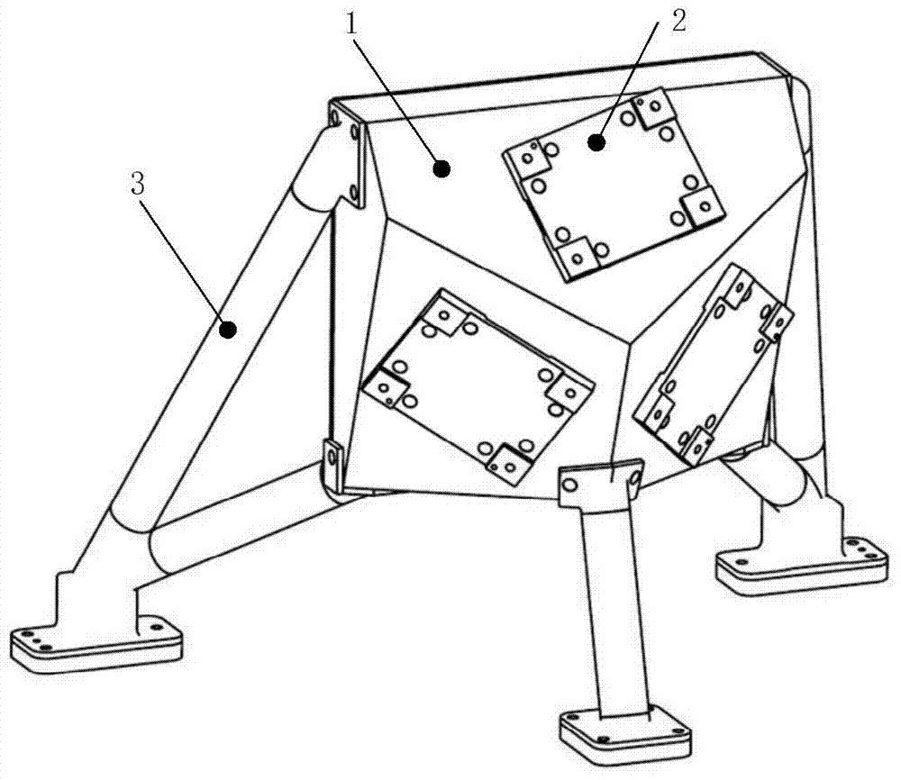
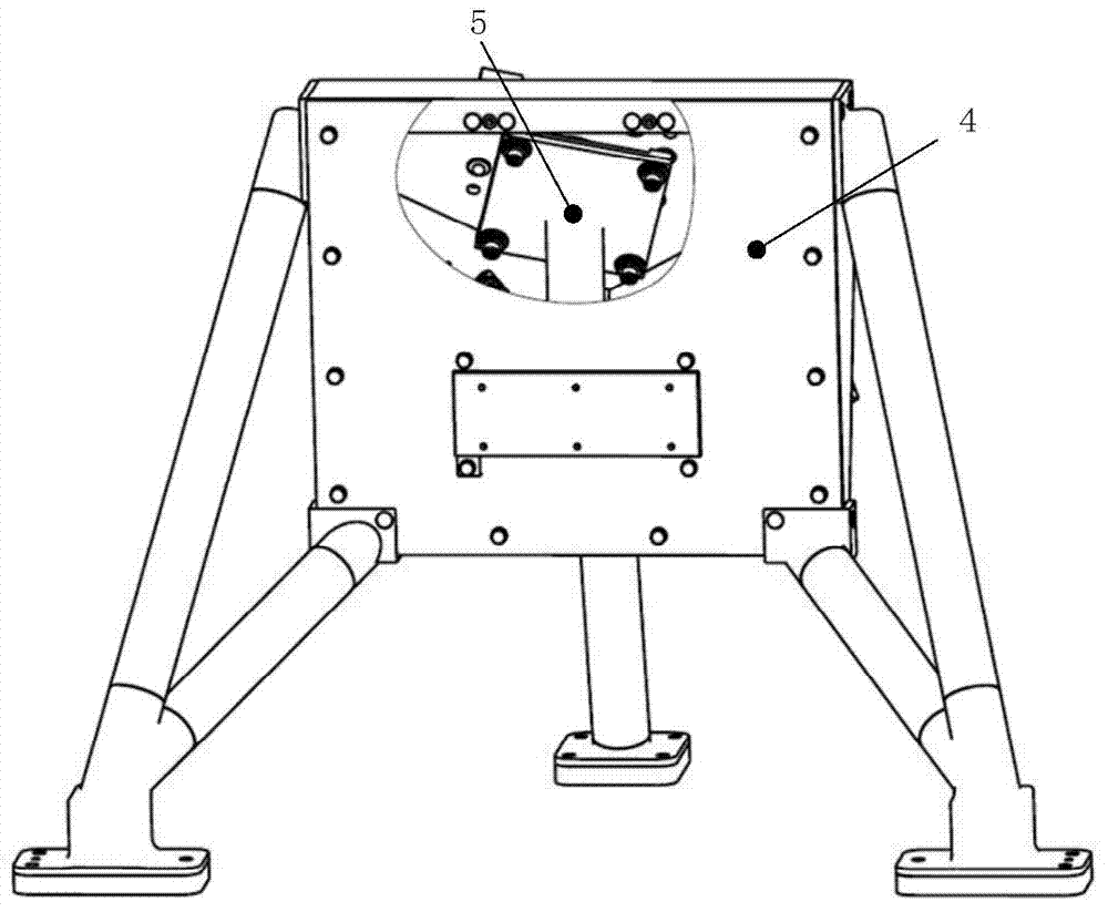
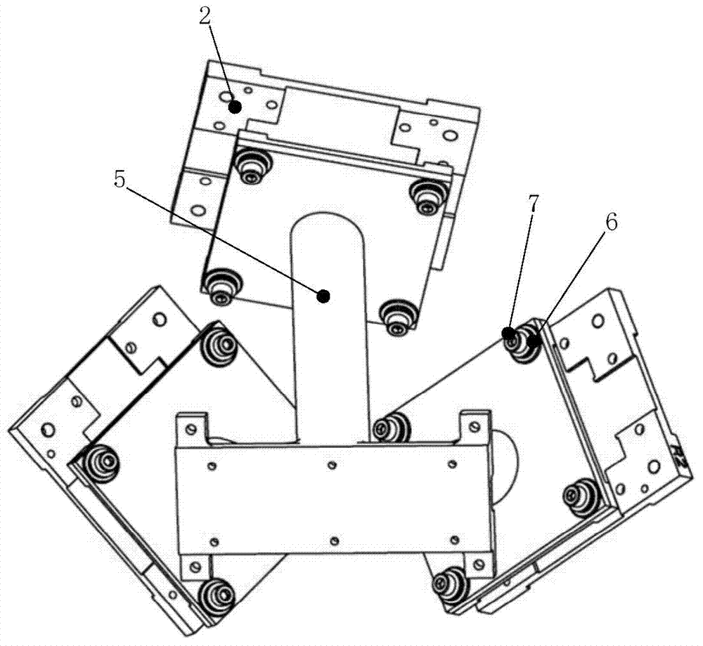
[0035] This embodiment provides a high-precision micro-deformation attitude control instrument installation structure for a spacecraft, including: a thin-walled shell structure, a cover plate, an instrument installation plate, a heat conductor, and a support rod assembly. Wherein: the instrument mounting plate has an I-shaped structure as a whole, including a first wing plate, a second wing plate and a web plate, and the first wing plate...


PUM


Abstract

The invention discloses a high-precision micro-deformation attitude control instrument installing structure for a spaceflight. An instrument installing plate comprises a first wing plate, a second wing plate and a web plate. The first wing plate is fixed to the outer surface of a thin-wall shell structure. The second wing plate is arranged in the thin-wall shell structure and connected with a plane butt-joint flange of a heat conducting body. The first wing plate and the second wing plate are connected through the web plate and carry out heat exchange through the web plate. The installing face of the heat conducting body is connected to a sealing cover plate which is connected with the thin-wall shell structure to form a head of the installing structure. One end of a supporting rod assembly is connected with the head of the installing structure. The other end of the supporting rod assembly is installed on a body of an optical imaging effective load structure of the spaceflight. The technical problem of rigorous thermal deformation of the attitude control instrument installing structure is solved, the installing structure has an excellent heat transfer property and a thermal deformation isolation property, the requirement for high-precision attitude determination and image navigation rectification of the spaceflight is met, and the installing structure has the advantages of being novel in structural form, light in mass and the like.

Description

technical field [0001] The invention relates to the technical field of spacecraft structure design, in particular to a high-precision micro-deformation attitude control instrument installation structure for a spacecraft. Background technique [0002] The installation of attitude control instruments for spacecraft is generally not directly installed on the structure of the spacecraft body, and often requires the transfer of a special installation structure. The installation structure provides an instrument mounting surface and a mounting surface with the spacecraft structure body. Conventional structures of this kind generally require light weight, high rigidity, good electrical conduction and heat transfer characteristics, and sufficient strength, so they are often machined from lightweight aluminum alloy or magnesium alloy materials. When the spacecraft is in orbit, these installation structures are in a harsh thermal environment that alternates repeatedly. Due to the high ...

Claims


Application Information

Patent Timeline
Patent Type & Authority Applications(China)
IPC IPC(8): B64G1/66
Inventor 王志国周徐斌任友良杨金军江世臣胡炳亭满孝颖
Owner SHANGHAI SATELLITE ENG INST
Why Eureka
Try Eureka