
Shield tunnel segment structure considering municipal cable pipelines and installing method

A shield tunnel segment and installation method technology, applied in tunnels, tunnel linings, mining devices, etc., can solve the problems of electrochemical corrosion of segments, easy to drill into the steel mesh, affecting the quality of segments, and avoid durability. Effects of damage, easy quality assurance and high technical reliability

Active Publication Date: 2015-07-01
JINAN RAILWAY TRANSPORT GRP CO LTD
View PDF5 Cites 20 Cited by
  • Summary
  • Abstract
  • Description
  • Claims
  • Application Information

AI Technical Summary

Problems solved by technology

Due to the need to drill holes on the shield segment, and the segment is laid with dense steel mesh during production, it is very easy to drill into the steel mesh when drilling, which not only affects the quality of the segment, causes water seepage of the structure, and often requires Re-drilling, in addition, the discarded boreholes need to be filled in time, resulting in unnecessary waste of financial resources and manpower
Compared with the cables required by the underground rail transit itself, the municipal cables are thicker in diameter and heavier in weight. If the cables are hung on the shield segments by drilling and supporting them, it will cause further deformation of the segments themselves and the joints between segments. Excessively large, causing water leakage in the tunnel
In addition, due to the wear of the cable protective layer during use, the current flows into the steel mesh on the shield segment through the cable support rod to form a potential difference, which further leads to electrochemical corrosion of the segment and affects the normal use of the structure

Method used


Image

  • Shield tunnel segment structure considering municipal cable pipelines and installing method
  • Shield tunnel segment structure considering municipal cable pipelines and installing method
  • Shield tunnel segment structure considering municipal cable pipelines and installing method

Examples


Embodiment Construction

[0048] Below in conjunction with accompanying drawing, implementation method of the present invention is described in detail:

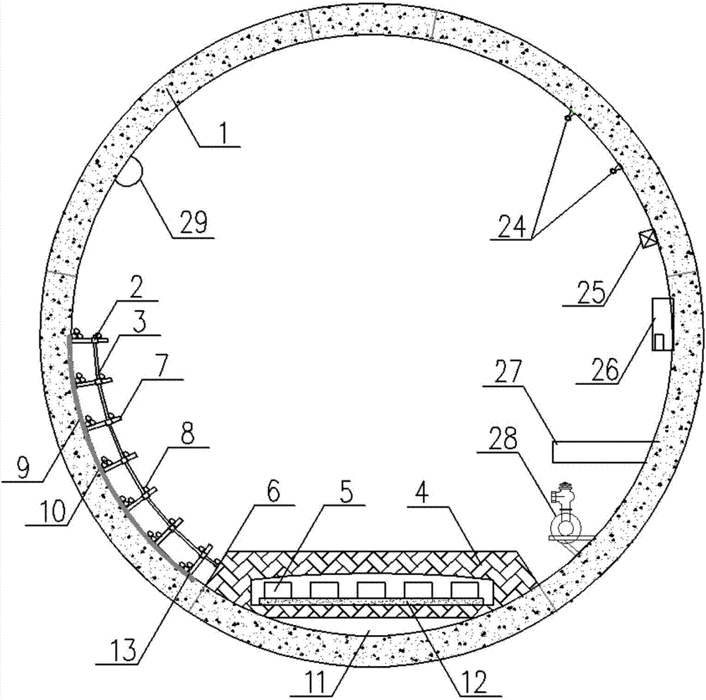
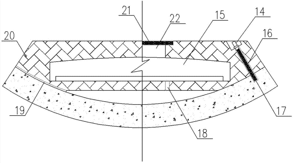
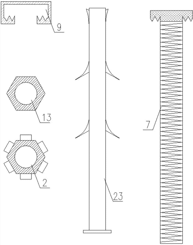
[0049] Underground tunnel segments that take into account municipal cables and pipelines: the shield tunnel is assembled through joints, and cable supports need to be laid on segment 1 where the two arch feet of the segment ring are located. The prefabricated segments at these two places are equipped with radial The pre-embedded channel 9 is located in the middle of the segment, the pre-embedded channel 9 is arranged along the curvature of the segment, and the notch is flush with the inner arc surface of the segment 1; Groove grooves are arranged on the inner sides of the two side walls on one side of the notch. The pre-embedded channel 9 is made of Q275 steel, coated with an electrical insulation layer.

[0050] Several cable support rods 7 are connected at different heights of the same pre-buried channel 9, the fixed end of the front side of the ca...


PUM


Abstract

The invention relates to a shield tunnel segment structure considering municipal cable pipelines and an installing method. According to the adopted technical scheme, pre-buried channels are formed in segments, needing laying of cable supports, in a shield tunnel; the fixed ends on the front sides of cable support rods are fixed to the segments on the side walls through the pre-buried channels, and the rear sides of the cable support rods point to the interior of the tunnel in a jetting-out mode; arc-shaped supports are connected to the rear middle portions of the cable support rods, and the other ends of the arc-shaped supports are connected to a track base; the municipal cable pipelines are placed on the cable support rods. The shield tunnel segment structure has the advantages of achieving the multi-purpose effect and being good in structural performance. The shield tunnel segments, the track base and the supports are pre-manufactured components, and therefore quality is easy to guarantee. The supports and the pre-buried channels are high in strength, resistant to electricity and fire, capable of being produced on a large scale, high in technology reliability, easy to construct and short in construction period.

Description

technical field [0001] The invention relates to a prefabricated segment of an underground rail shield tunnel and a preparation method thereof. The prefabricated segment of the shield tunnel is especially used for installing municipal cables in large-diameter underground rail transit shield tunnels. Background technique [0002] With the continuous acceleration of the urbanization process and the increasing consumption of underground space resources, the difficulty of constructing traditional underground cable channels is increasingly affected by the construction of urban rail transit and other underground municipal pipelines. In the construction of underground rail transit, by increasing the diameter of the tunnel and reserving space for the cable pipeline, while connecting the traffic in the urban area, the high-voltage transmission line is connected through the underground tunnel and introduced into the central urban area, which alleviates the power transmission to the cent...

Claims


Application Information

Patent Timeline
IPC IPC(8): E21D11/04
CPCE21D11/08E21F17/02
Inventor 王国富
Owner JINAN RAILWAY TRANSPORT GRP CO LTD
Learn More