

Paralleling model semi-active vibration isolator
A semi-active, vibration isolator technology, applied in the direction of shock absorber, shock absorber-spring combination, shock absorber, etc. Damage and other problems, to achieve the effect of improving service life, increasing stiffness and reducing vibration
- Summary
- Abstract
- Description
- Claims
- Application Information
AI Technical Summary
Problems solved by technology
Method used
Image

Examples
Embodiment 1
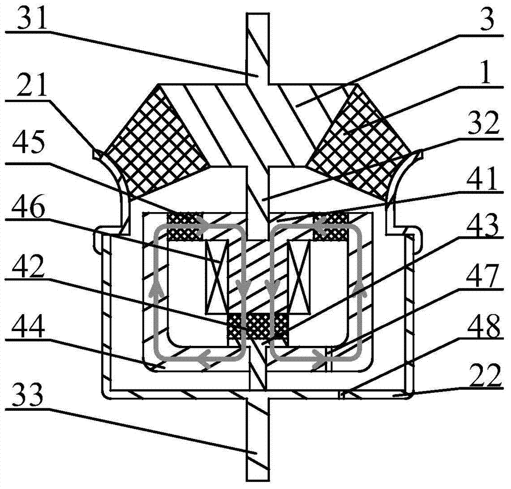
[0025] see figure 1 , the structural form of the parallel mode semi-active vibration isolator in this embodiment is:
[0026] A cylindrical upper casing 21 is provided, the rubber main spring 1 is blocked in the top opening of the upper casing 21, the main spring skeleton 3 runs through the rubber main spring 1, and upper and lower ends of the main spring skeleton 3 are respectively provided with upper The connecting stud 31 and the lower connecting stud 32, the upper end of the upper connecting stud 31 is used to connect with the main vibrating object, and transmits the vibration energy of the main vibrating object, and the lower end of the lower connecting stud 32 is used for and is wound with an excitation coil 46 columnar iron cores 41 are connected, and the columnar iron cores 41 are supported in the magnetic sleeve 44 through the shear magnetorheological elastomers 45 arranged on the outer circumference of the columnar iron cores, and the two sides of the extruded magnet...
Embodiment 2
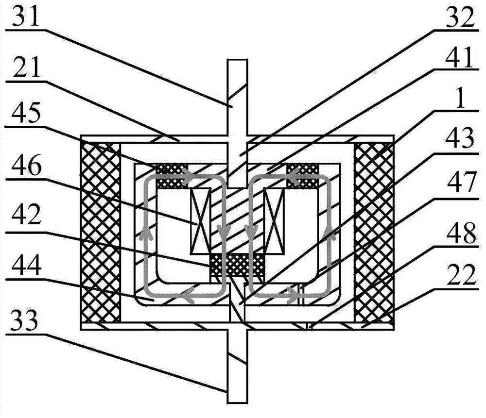
[0031] see figure 2 , the structural form of the parallel mode semi-active vibration isolator in this embodiment is:
[0032] A ring-shaped rubber main spring 1 is provided, and the upper casing 21 and the lower casing 22 are respectively connected with the top end and the bottom end of the rubber main spring 1 to form a vibration isolator shell cavity, and the upper end and the lower end of the upper casing 21 are fixed respectively. There are an upper connecting stud 31 and a lower connecting bolt 32, wherein the upper end of the upper connecting bolt 31 is used to connect with the main vibrating object, and the lower end of the lower connecting bolt 32 is used to connect with the cylindrical iron core 41 wound with an excitation coil 46. connection, the columnar iron core 41 is supported in the magnetic sleeve 44 through the shearing magnetorheological elastomer 45 arranged on the outer circumference of the columnar iron core, and the two ends of the extruded magnetorheolo...
PUM
 Abstract
Description
Claims
Application Information