
Calculating method of attitude matrix and positioning navigation method based on attitude matrix

A matrix calculation and azimuth technology, applied in the field of information, can solve problems such as slow calculation speed, software cannot be positioned normally, and attitude data software cannot have a unified interface and general sharing, etc.

Active Publication Date: 2015-07-01
武汉雄楚高晶科技有限公司
View PDF6 Cites 27 Cited by
  • Summary
  • Abstract
  • Description
  • Claims
  • Application Information

AI Technical Summary

Problems solved by technology

[0005] (1) First, a large number of trigonometric functions need to be used to reconstruct the attitude matrix, resulting in slow calculation speed;
[0006] (2) The rotation angles of the three angles relative to the coordinate system are not uniform;
[0007] (3) There is no unified standard for the conversion order of the three angles. The definition of the order of the three angles on different navigation devices is different. There is no unified standard, which leads to the inability of a unified interface and common use of attitude data software for different navigation devices Therefore, the lack of a unified attitude data standard greatly hinders the development of navigation technology
[0008] The positioning algorithm used in some software is not based on images, and the software cannot be positioned normally without GPS and wifi. The camera scanning interface effect in the software gives people a sense of image recognition and positioning
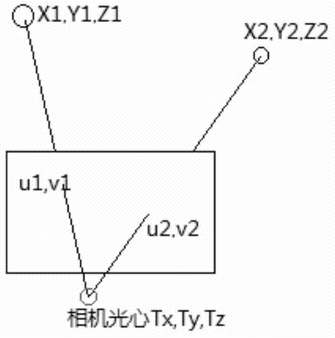
The traditional image positioning method does not know the attitude data, so it requires at least three pairs of corresponding points of the same name of the object image to perform positioning calculations. In fact, the three pairs of the same name points need to calculate the attitude in addition to positioning, so the obtained result It is very unstable and inaccurate, especially if there is a straight line at three points or the distance between the three points is very small, there will be very unstable and inaccurate problems. The reason is that these three points have to bear attitude calculations in addition to positioning calculations.
[0009] The potential applications of various aspects of smart machine attitude data mentioned in the present invention include attitude pointing, video (image) correction, 3D remote control, 3D navigation, target superposition, and information superposition between smart machine video and map images. It has not been applied in the field of light and cheap smart machines

Method used


Image

  • Calculating method of attitude matrix and positioning navigation method based on attitude matrix
  • Calculating method of attitude matrix and positioning navigation method based on attitude matrix
  • Calculating method of attitude matrix and positioning navigation method based on attitude matrix

Examples


Embodiment approach

[0184] Assuming that the head of the smartphone is defined as the main direction, the vector of the head relative to the coordinate system of the smartphone is p={0,1,0} T

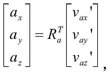
[0185] then p ┴ =R g T p={r 21 r 22 r 23} T where r ij is the element in row i and column j of the R matrix.

[0186]Assuming that the right side of the smartphone is defined as the main direction, the vector on the right side relative to the coordinate system of the smartphone is p={1,0,0} T

[0187] then p ┴ = R g T p={r 11 r 12 r 13} T

[0188] Method 2 Navigation Service

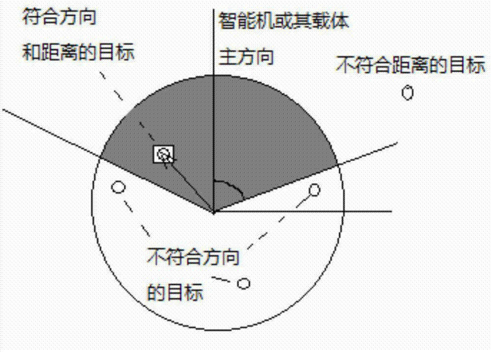
[0189] Fix the smart machine with a certain carrier, such as a vehicle and boat, and define the vector p of the main direction of the carrier relative to the smart machine itself.

[0190] Draw the vector principal direction vector p in the map in real time ┴ = R T p and target vector v o A schematic diagram of the relationship between.

[0191] Calculate the cosine cos(dφ)>cos(φa) of the included angle to ...

specific Embodiment approach

[0208] The smart phone is required to be placed horizontally, and the angle between the main direction angle vector and the smart phone to the target vector, or the dot product between the two, is obtained by using the first value value[0] of the direction sensor.

[0209] Calculate the target vector v on the 2D map o ={v ox , v oy} azimuth φ vo The inverse trigonometric function atan2(v oy ,v ox ) to achieve, calculate φ angle and φ vo The included angle of the vector formed by the angle on the plane

Embodiment approach

[0210] Implementation methods, using but not limited to the following methods:

[0211] φ angle and φ vo The angle between can be calculated as follows:

[0212]

[0213] Generally, the 2-dimensional dot product is used to calculate the φ angle and φ vo The cosine of the angle between = ({cosφ, sinφ} dot product v o ) / |v o |, if the cosine value>cos(φa) is considered to be in the same direction.

[0214] In order to facilitate user interactive control, the target vector v on the map o Draw simultaneously with the smart machine vector {cosφ, sinφ}. Especially when the target is not within the field of view of the map, the drawing direction at the intersection of the line from the smartphone to the target and the border of the map is v o arrow pointing to the target.

[0215] Real-time correction of video images based on attitude data of intelligent machines

[0216] The general method steps are as follows:

[0217] 1. Adopt the method of claim 1 to obtain the attitu...


PUM


Abstract

Disclosed are attitude determination, panoramic image generation and target recognition methods for an intelligent machine. The attitude determination method for the intelligent machine comprises the following steps: defining a local coordinate system; and determining an intelligent machine attitude matrix Rg, wherein Rg is a 3x3 unit orthogonal matrix relative to the local coordinate system and can be obtained through multiple methods according to different sensors inside the intelligent machine. By means of attitude determination of the intelligent machine, multiple applications can be achieved, comprising a virtual reality roaming method for the intelligent machine, multi-vision localization of the intelligent machine, monocular single-point localization of the intelligent machine, panoramic image generation of the intelligent machine, target direction selection in the intelligent machine, real-time video image correction, single-image localization of the intelligent machine, and relative localization among multiple cameras.

Description

technical field [0001] The invention relates to the field of information technology, in particular to a calculation method of an attitude matrix and a positioning and navigation method based on the attitude matrix. Background technique [0002] Geographical information location services have always only emphasized spatial positioning and spatial distance, but ignored a very important data and concept - posture. In fact, users are more concerned about the direction of the destination or target relative to themselves. Location services without posture are incomplete location services. For example, in a taxi-hailing software, if the driver only considers the distance when grabbing a ticket, he may choose the passenger behind him. Since the lane cannot go against the direction, the driver cannot pick up the passenger, and the passenger cannot take a taxi. When fighting, if you only know that the enemy is approaching but not from which direction the enemy is approaching, this wi...

Claims


Application Information

Patent Timeline
IPC IPC(8): G01C21/20H04W4/021
CPCG06F19/00G01C21/08G01C21/12G01C21/20G06T19/006G06V20/20G01C21/1654H04W4/021H04W4/027
Inventor 刘进
Owner 武汉雄楚高晶科技有限公司
Learn More