
CT system and method thereof

A CT image and motion direction technology, applied in image enhancement, instrumentation, image data processing, etc., can solve problems such as multi-scanning time, missed reporting, and restriction of security inspection efficiency, and achieve the effect of speeding up the scanning process

Active Publication Date: 2015-07-01
TSINGHUA UNIV +1
View PDF5 Cites 12 Cited by
  • Summary
  • Abstract
  • Description
  • Claims
  • Application Information

AI Technical Summary

Problems solved by technology

The first is the problem of scanning speed. Faster inspection speed can help relieve the pressure brought by passenger flow and cargo flow, and fast scanning usually requires a higher speed slip ring. Due to processing accuracy and reliability issues, the cost of high-speed slip rings is very high. Expensive, high maintenance costs, difficult to promote
The second is the problem of false positives and false negatives. The automatic identification and alarm function of CT technology is difficult to achieve 100% accuracy. The inspection of contraband still needs manual assistance to judge, and even open the package for inspection. Usually, it takes several minutes or even more than a dozen for an open package inspection. Minutes, which greatly increases the cost of manpower and time, and seriously restricts the improvement of security inspection efficiency
In order to alleviate this problem, there are currently devices using secondary scanning technology on the market, which can improve the quality of CT images and reduce the number of unpacking inspections by performing secondary high-precision scanning on suspicious bags. There are problems such as taking up more scanning time and interrupting the security check process

Method used


Image

  • CT system and method thereof
  • CT system and method thereof
  • CT system and method thereof

Examples


Embodiment Construction

[0023] Specific embodiments of the present invention will be described in detail below, and it should be noted that the embodiments described here are only for illustration, not for limiting the present invention. In the following description, numerous specific details are set forth in order to provide a thorough understanding of the present invention. It will be apparent, however, to one of ordinary skill in the art that these specific details need not be employed to practice the present invention. In other instances, well-known circuits, materials or methods have not been described in detail in order to avoid obscuring the present invention.

[0024] Throughout this specification, reference to "one embodiment," "an embodiment," "an example," or "example" means that a particular feature, structure, or characteristic described in connection with the embodiment or example is included in the present invention. In at least one embodiment. Thus, appearances of the phrases "in on...


PUM


Abstract

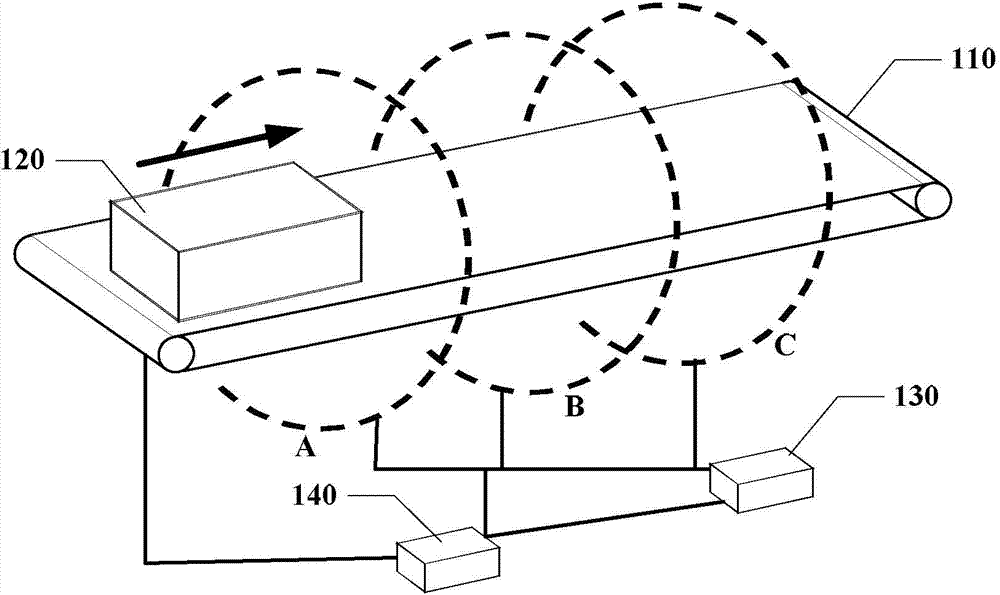
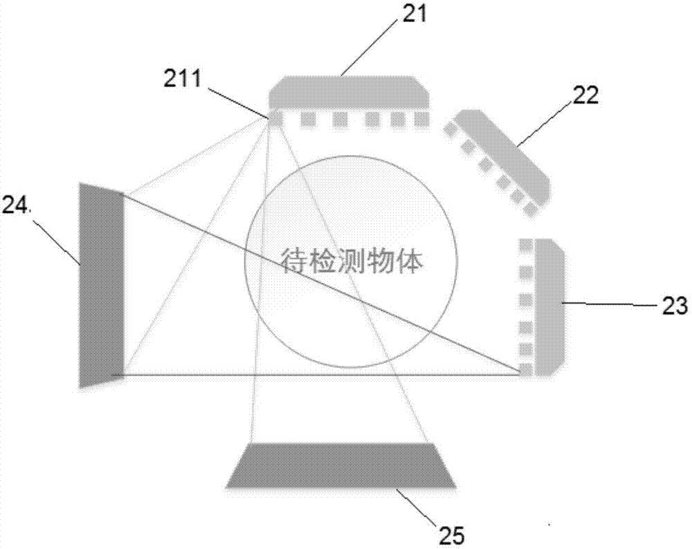
A CT system and method thereof are discloses. The system includes: a fixed multi-plane multi-source X-ray generation device and a control system thereof that provide X-ray source used in luggage inspection; a single-energy, pseudo-dual-energy or spectral detector system and data transfer system that receive perspective data of X ray penetrating the luggage, and transfer the data to a computer for processing; a conveyor (110) and a control system thereof that control a speed for moving the luggage forth and back, and perform tomogram scanning; and a host computer system that performs tomogram reconstruction and provides man-machine interaction. The system takes full advantage of characteristics, such as high speed and stability, brought by the distributed ray sources which replace the normal slip ring technology. The system also adopts the idea of inverse-geometry CT, and reduces detector area and cost by increasing the number of ray sources. With the reduction of detector area, cone-beam artifacts and cup-shape artifacts caused by scattering are also reduced, and influence of the oblique effect on registration of dual-energy data is suppressed.

Description

technical field [0001] Embodiments of the present invention relate to the field of radiation imaging safety detection, and in particular to a multi-source static CT baggage safety inspection system and method thereof. Background technique [0002] CT technology has played an important role in security inspection due to its ability to eliminate the effect of overlapping objects. Traditional CT uses a slip ring device to obtain projection data at different angles through the rotation of the X-ray machine and the detector, and obtains tomographic images through reconstruction methods to obtain the internal information of the detected luggage items. Cooperating with dual-energy or multi-energy imaging technology, the current luggage inspection equipment can reconstruct the atomic number and electron density of the substance to be inspected, so as to realize the identification of the substance type, which plays a very good role in the detection of explosives and dangerous goods. ...

Claims


Application Information

Patent Timeline
IPC IPC(8): G01N23/04
CPCG06T7/0002G06T2207/30112G01V5/005G01V5/226
Inventor 陈志强张丽赵骥黄清萍金鑫
Owner TSINGHUA UNIV
Learn More