Reaction chamber heating control method and device
A heating control device and heating control technology, applied in auxiliary controllers with auxiliary heating devices, temperature control using electric methods, etc., can solve problems such as large heating power load, heating and aging lines, and failure of the heating system to work normally , to achieve the effect of reducing adverse effects and heating uniformly
- Summary
- Abstract
- Description
- Claims
- Application Information
AI Technical Summary
Problems solved by technology
Method used
Image

Examples
Embodiment 1
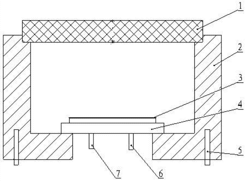
[0125] The selected single heater 5 has a power of 400w, and the reaction chamber 2 is heated from room temperature to 93°C for 20 minutes, and the required heating power is 1100w, see Figure 7 , Figure 8 shown.
[0126] Figure 7 It is the temperature measurement data diagram of the reaction chamber 2 before the heater 5 is disconnected, Figure 8 In order to heat to 31mim, the temperature measurement data diagram of one of the other three heaters 5 not located on the side of the main temperature sensor 8 is disconnected. According to the data analysis in the figure, before the heater is disconnected, the temperature difference between the temperature of the main temperature sensor 8 and the temperature of the auxiliary temperature sensor 10 does not exceed a temperature value x, where x is defined according to the experimental results. After one of the other three heaters 5 not located on the side of the main temperature sensor 8 is disconnected, at 35 minutes, the diff...
Embodiment 2
[0129] The selected single heater 5 has a power of 300w, and the reaction chamber 2 is heated from room temperature to 93°C for 20 minutes, and the required heating power is 1100w, see Figure 9 , Figure 10 shown.
[0130] Figure 9 It is the temperature measurement data diagram of the reaction chamber 2 before the heater 5 is disconnected, Figure 10 For heating to 31mim, the temperature measurement data diagram of one of the other three heaters 5 that are not located on the side of the main temperature sensor 8 is disconnected. According to the data analysis in the figure, before the heater is disconnected, the temperature difference between the temperature of the main temperature sensor and the auxiliary temperature sensor does not exceed a temperature value x, where x is defined according to the experimental results. After one of the other three heaters not located on the side of the main temperature sensor 8 is disconnected, at 35 minutes, the difference y between the...
Embodiment approach
[0150] As a possible implementation manner, the comparison unit 220 includes a first comparison subunit 221 and a second comparison subunit 222;
[0151] The first comparison subunit 221 is used to judge that the main temperature sensor 8 side The heater 5 of the heater 5 is not faulty, and at least one heater 5 in the other three heaters 5 has a fault, then the first fault alarm signal that the other heaters 5 are disconnected is sent;
[0152] The second comparison subunit 222 is used to determine that the heater 5 on the side of the main temperature sensor 8 is faulty when the temperature x1 of the main temperature sensor 8 is lower than the temperature x2 of the auxiliary temperature sensor 10, and send a heating signal on the side of the main temperature sensor 8. The second fault alarm signal that the device 5 is disconnected;
PUM
 Abstract
Description
Claims
Application Information
 - Generate Ideas
- Intellectual Property
- Life Sciences
- Materials
- Tech Scout
- Unparalleled Data Quality
- Higher Quality Content
- 60% Fewer Hallucinations
Browse by: Latest US Patents, China's latest patents, Technical Efficacy Thesaurus, Application Domain, Technology Topic, Popular Technical Reports.
© 2025 PatSnap. All rights reserved.Legal|Privacy policy|Modern Slavery Act Transparency Statement|Sitemap|About US| Contact US: help@patsnap.com