
Nuclear power plant container pressurized energy storage system

A technology for nuclear power plants and containers, which is applied in the field of pressurized energy storage systems for nuclear power plants, can solve problems such as the inability of cooling water to be transported into spent fuel pools, and achieve the effects of preventing nuclear radiation disasters and improving safety and reliability.

Active Publication Date: 2018-01-26
CHINA GENERAL NUCLEAR POWER CORP +1
View PDF5 Cites 0 Cited by
  • Summary
  • Abstract
  • Description
  • Claims
  • Application Information

AI Technical Summary

Problems solved by technology

[0005] The purpose of the present invention is to overcome the shortcomings of the above-mentioned prior art, and provide a nuclear power plant container pressurized energy storage system, which aims to solve the problem that the cooling water in the water tank cannot be delivered to the spent fuel pool in the case of failure of the electric drive system in the nuclear power plant technical problem

Method used


Image

  • Nuclear power plant container pressurized energy storage system
  • Nuclear power plant container pressurized energy storage system

Examples


Embodiment Construction

[0027] In order to make the object, technical solution and advantages of the present invention clearer, the present invention will be further described in detail below in conjunction with the accompanying drawings and embodiments. It should be understood that the specific embodiments described here are only used to explain the present invention, not to limit the present invention.

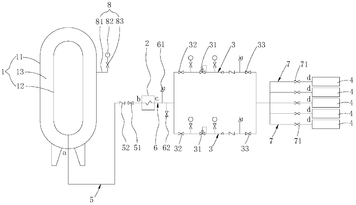
[0028] The pressurization process of the nuclear power plant container pressurized energy storage system provided by the embodiment of the present invention is mainly explained by using the pressurization of the water tank used to supply water to the spent fuel pool as an example, so as to ensure that when an earthquake and a tsunami occur at the same time or other extreme weather occurs, the power In the event of failure of the drive system, there is sufficient pressure in the water tank to discharge the water to the outside. Of course, in specific applications, the nuclear power plant container p...


PUM


Abstract

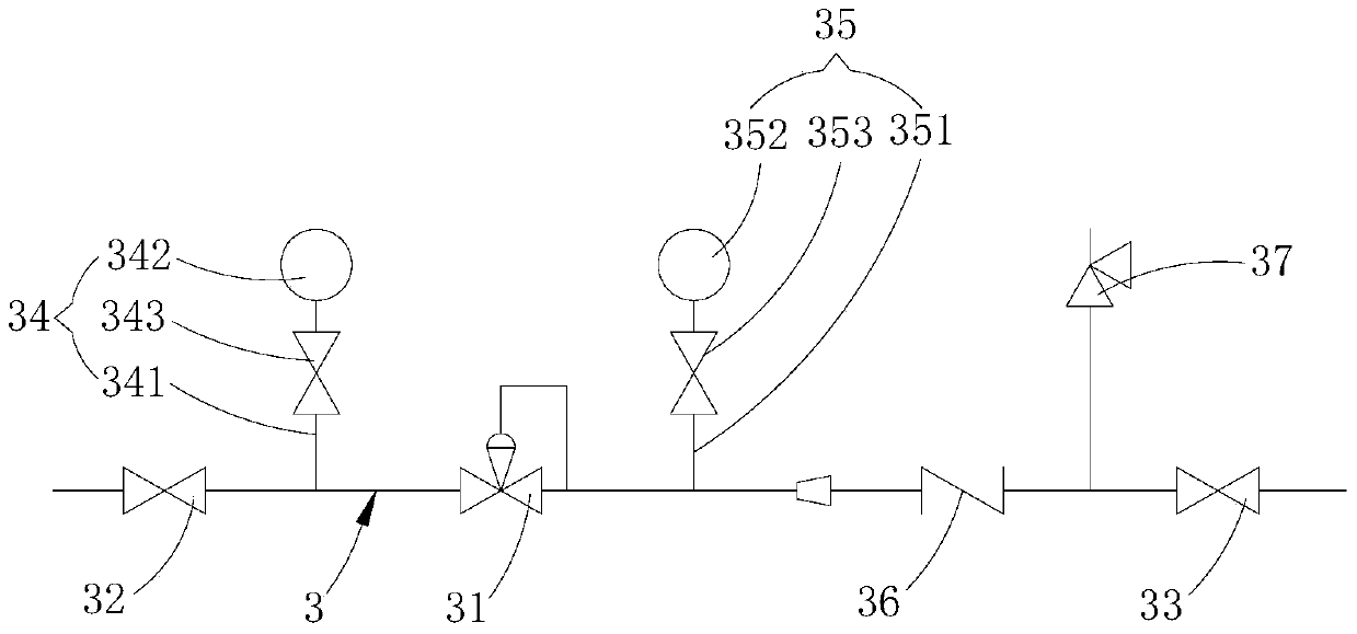
The invention is applicable to the field of a container pressurizing system in a nuclear power station and discloses a container pressurizing and energy-storage system in the nuclear power station for pressurizing the inner part of a water tank so as to enable cooling water in the water tank to be conveyed outwards. The container pressurizing and energy-storage system comprises a storage tank, a liquid compressed medium stored in the storage tank, a vaporizer with an inlet and an exhausting port and used for vaporizing the liquid compressed medium, a pressure reducing pipeline with a pressure reducing valve, the water tank with a gas inlet, a first pipeline for connecting an outlet of the storage tank and the inlet of the vaporizer, a second pipeline for connecting the exhausting port of the vaporizer and the pressure reducing pipeline, and a third pipeline for connecting the pressure reducing pipeline and the gas inlet of the water tank, wherein the first pipeline and the third pipeline are respectively provided with a first stopping valve and a second stopping valve; the two ends of the pressure reducing pipeline are respectively provided with a third stopping valve and a fourth stopping valve; and the pressure reducing valve is arranged between the third stopping valve and the fourth stopping valve. The container pressurizing and energy-storage system disclosed by the invention has the advantage that the problem that the cooling water in the water tank can not be conveyed into a spent-fuel pool under the condition of failure of an electric driving system in the nuclear power station is effectively solved.

Description

technical field [0001] The invention belongs to the field of nuclear power plant container pressurization systems, in particular to a nuclear power plant container pressurized energy storage system. Background technique [0002] Spent fuel is nuclear fuel that has been burned in the reactor. During the storage of spent fuel, due to its own exothermic reaction, a large amount of heat will be released. Therefore, spent fuel must be effectively cooled during storage to prevent spent fuel from melting. Spent fuel pools are water pools used to store spent fuel in nuclear power plants. Spent fuel has an exothermic reaction and strong radiation. In order to meet the cooling requirements of spent fuel and prevent radiation leakage, the water level in the spent fuel pool is generally required to be kept higher than the spent fuel and to be cooled by forced circulation. We know that under accident conditions, once the forced circulation cooling of the spent fuel pool is lost, the hea...

Claims


Application Information

Patent Timeline
Patent Type & Authority Patents(China)
IPC IPC(8): G21C15/18G21C15/243
CPCG21C15/18G21C15/243Y02E30/30
Inventor 蒲江张士朋林鸿江陈士强
Owner CHINA GENERAL NUCLEAR POWER CORP
Learn More