
Reactive compensation equipment with LED (light emitting diode) constant-current driver

A compensation equipment, constant current drive technology, applied in reactive power compensation, reactive power adjustment/elimination/compensation, lighting and heating equipment, etc. Adaptation and other problems to achieve the effect of meeting the requirements of LED service life, convenient maintenance and repair, and less electromagnetic interference

Active Publication Date: 2015-07-01
NANJING UNIV OF AERONAUTICS & ASTRONAUTICS
View PDF4 Cites 4 Cited by
  • Summary
  • Abstract
  • Description
  • Claims
  • Application Information

AI Technical Summary

Problems solved by technology

The life of electrolytic capacitors is generally within 10,000 hours and is seriously affected by temperature, which is not suitable for the life of LEDs of more than 50,000 hours.
Of course, there are also driving solutions without electrolytic capacitors, but the topological structure of the power part, the hardware and software of the driving control part of these solutions are relatively complicated, which is not good for later maintenance and repair, which is one of the reasons why LED lighting has not been popularized yet.

Method used


Image

  • Reactive compensation equipment with LED (light emitting diode) constant-current driver

Examples


Embodiment Construction

[0016] The present invention will be further described below in conjunction with accompanying drawing.

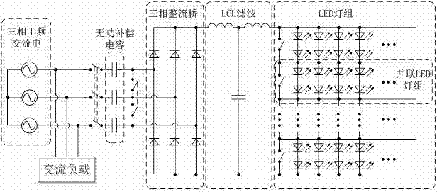
[0017] The schematic diagram of the circuit structure of the present invention is as figure 1 As shown, it includes three-phase power frequency AC power supply, reactive power compensation capacitor, three-phase rectifier bridge, LCL filter and LED lamp group connected in sequence, where each phase of the three-phase power frequency AC power is connected to a reactive power compensation capacitor through a switch One end and the other end of the reactive power compensation capacitor are connected to the midpoint of the corresponding bridge arm on the three-phase input side of the three-phase rectifier bridge. On the side of the reactive power compensation capacitor close to the rectifier bridge, there are two switches. When the two switches When the conduction is closed at the same time, the three reactive power compensation capacitors form a star connection. In order to m...


PUM


Abstract

The invention provides reactive compensation equipment with an LED (light emitting diode) constant-current driver. The reactive-load compensation equipment with the LED constant-current driver comprises a three-phase power frequency alternating-current power supply, reactive compensation capacitors, a three-phase rectifier bridge, an LCL (lower control limit) filter and an LED lamp bank which are sequentially connected to one another; each phase of the three-phase power frequency alternating-current power supply is connected with one end of the corresponding reactive compensation capacitor through a corresponding switch; the other ends of the reactive compensation capacitors are connected to midpoints, which correspond to a bridge arm, of three-phase inputting sides of the three-phase rectifier bridge; two switches are arranged on one side, which is close to the rectifier bridge, of each reactive compensation capacitor; and when the two switches of each reactive compensation capacitor are switched on simultaneously, the three reactive compensation capacitors are connected to one another in a star-shaped manner. By the reactive compensation equipment, reactive compensation can be realized, the latter LED driver does not need an electrolytic capacitor, the service life is long, a complex controller is not required, and the reactive compensation equipment with the LED constant-current driver is maintained and repaired conveniently in the later period, has important using value for places needing reactive compensation, is suitable for workshops at which a large number of inductive loads are used, and is also suitable for places needing reactive compensation and illumination such as a power distribution room with a transformer.

Description

technical field [0001] The invention relates to the technical field of power electronics, in particular to a reactive power compensation device with LED constant current drive. Background technique [0002] In recent years, energy conservation has always been a hot topic. Since the "Eleventh Five-Year Plan", relevant government departments have always attached great importance to energy conservation and emission reduction. In energy saving and emission reduction, a very important part is the energy saving of lighting electricity. Today, countries around the world are gradually banning the sale and use of incandescent lamps. Obviously, incandescent lamps can no longer meet the needs of the times. LED lights have high brightness, high efficiency, long life, and small size. Under such an era background, they can replace other lighting equipment to achieve the purpose of energy saving and emission reduction. LED is the abbreviation of Light Emitting Diode. The Chinese name is ...

Claims


Application Information

Patent Timeline
IPC IPC(8): H02J3/18H05B37/02
CPCF21V23/04H02J3/18H05B47/10Y02E40/30
Inventor 杨袁钰周波钱振宇石宝平秦显慧
Owner NANJING UNIV OF AERONAUTICS & ASTRONAUTICS
Learn More