Stator magnetic circuit structure for axial magnetic circuit permanent magnet motor

A technology of permanent magnet motor and axial magnetic circuit, applied in the direction of magnetic circuit shape/style/structure, magnetic circuit static parts, etc., can solve the problems of magnetic circuit design difficulties, axial magnetic circuit structure does not have two-dimensional characteristics, etc.

Inactive Publication Date: 2015-07-01
HARBIN INST OF TECH
View PDF6 Cites 3 Cited by
  • Summary
  • Abstract
  • Description
  • Claims
  • Application Information

AI Technical Summary

Problems solved by technology

The axial magnetic circuit structure does not have two-dimensional features, which brings difficulties to the magnetic circuit design

Method used


Image

  • Stator magnetic circuit structure for axial magnetic circuit permanent magnet motor
  • Stator magnetic circuit structure for axial magnetic circuit permanent magnet motor
  • Stator magnetic circuit structure for axial magnetic circuit permanent magnet motor

Examples


specific Embodiment approach 1

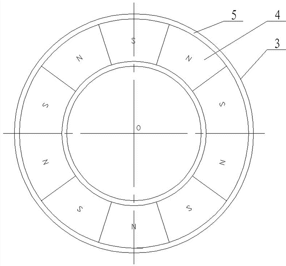
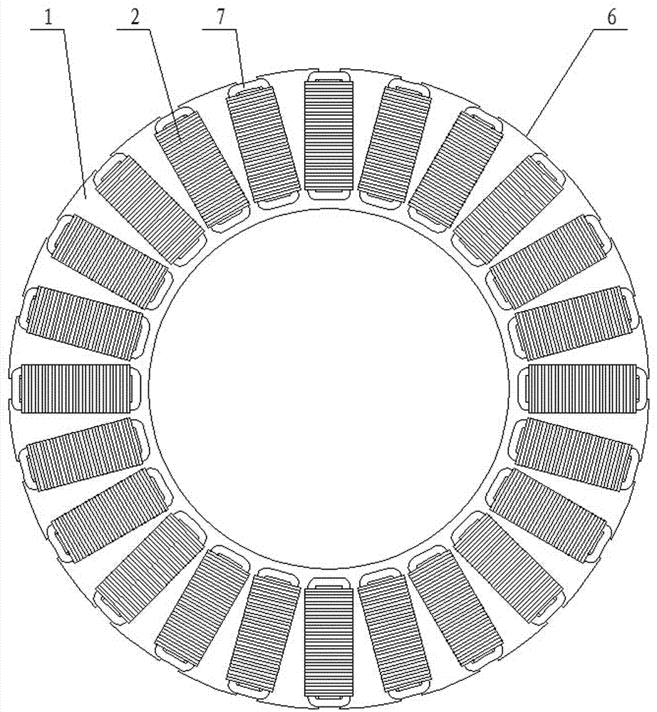
[0021] Specific implementation mode one: as Figure 2~Figure 5 As shown, a stator magnetic circuit structure for an axial magnetic circuit permanent magnet motor is composed of a circular stator yoke 1 and a plurality of stator tooth blocks 2, and each of the stator tooth blocks 2 is from the tooth tail to the The tooth top is sequentially composed of a T-shaped tooth tail 2-1, a tooth body 2-2 and a tooth tip 2-3. The outer peripheral surface of the annular stator yoke 1 is provided with a plurality of T-tail slots 1 in the radial direction. -1, the plurality of T tail slots 1-1 are evenly distributed along the outer circumferential surface of the annular stator yoke 2, and the number of the plurality of T tail slots 1-1 is the same as the number of the plurality of stator tooth blocks 2 ; The width and height of the T-tail slot 1-1 are the same as the width and height of the T-shaped tooth tail 2-1 on the stator tooth block 2, and a stator tooth block 2 is embedded in each T...

specific Embodiment approach 2

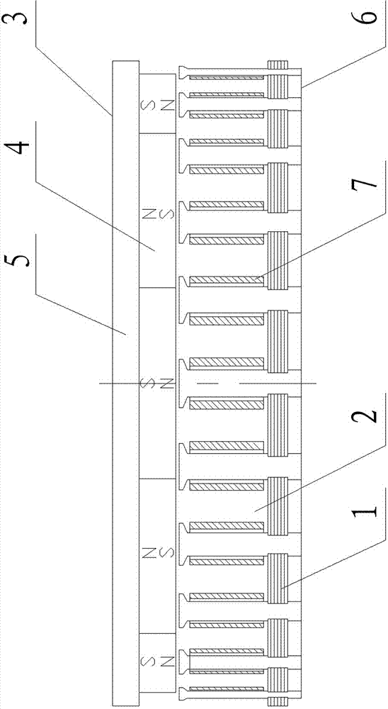
[0022] Specific implementation mode two: as figure 2 , image 3 , Figure 5 , Figure 7 and Figure 8 As shown in the first embodiment, a stator magnetic circuit structure for an axial magnetic circuit permanent magnet motor, each of the stator tooth blocks 2 is stacked by several pieces of silicon steel sheet punched and riveted. Or bonded together to form. The effect is: on the one hand, it can improve the utilization rate of materials and facilitate the assembly of the motor stator; on the other hand, the magnetic circuit of the motor has the characteristics of an axial magnetic circuit, and there is no abnormal iron loss.

specific Embodiment approach 3

[0023] Specific implementation mode three: as Figure 2~Figure 4 and Figure 8 As shown in the specific embodiment 1 or 2, a stator magnetic circuit structure for an axial magnetic circuit permanent magnet motor, the circular stator yoke 1 is stacked by several circular silicon steel sheet punches and adopts Riveted or glued together to form. The effect is: on the one hand, it can improve the utilization rate of materials and facilitate the assembly of the motor stator; on the other hand, the magnetic circuit of the motor has the characteristics of an axial magnetic circuit, and there is no abnormal iron loss.


PUM


Abstract

The invention provides a stator magnetic circuit structure for an axial magnetic circuit permanent magnet motor, and belongs to the technical field of motors. The stator magnetic circuit structure for the axial magnetic circuit permanent magnet motor is suitable for characteristics of a magnetic circuit of the axial magnetic circuit motor, and has normal iron loss. A plurality of T tail grooves are formed in the outer peripheral surface of a ring-shaped stator yoke along the radial direction and are uniformly distributed along the outer periphery of the ring-shaped stator yoke; the number of the T tail grooves is the same with that of a plurality of stator tooth blocks; the widths and the heights of the T tail grooves are the same with those of T-shaped tooth tails on the stator tooth blocks; a stator tooth block is inlaid in each T tail groove; and the T-shaped tooth tail of each stator tooth block is in close fit with the corresponding T tail groove. On the axial magnetic circuit permanent magnet motor, the trend of tooth magnetic flux and the trend of yoke magnetic flux are consistent to a punching direction, and abnormal iron loss can be avoided.

Description

technical field [0001] The invention relates to a permanent magnet motor for an axial magnetic circuit, belonging to the technical field of motors. Background technique [0002] Permanent magnet motors can adopt radial magnetic circuit structure or axial magnetic circuit structure. Most of the current permanent magnet motors adopt a radial magnetic circuit structure, because the magnetic circuit is characterized by the fact that the magnetic circuits of the stator teeth and the yoke are on the same plane, showing two-dimensional characteristics, and can be easily stacked with the same punching sheet. become. The axial magnetic circuit structure does not have two-dimensional features, which brings difficulties to the magnetic circuit design. But in some cases, such as in super-large motors, the axial magnetic circuit structure has the advantage of easy installation. Therefore, it is necessary to create a stator magnetic circuit structure that is suitable for the magnetic c...

Claims


Application Information

Patent Timeline
IPC IPC(8): H02K1/14
Inventor 邹继斌陆永平徐永向赵猛胡建辉李勇
Owner HARBIN INST OF TECH
Why Eureka
Try Eureka