
Millimeter-wave even harmonic mixer structure

An even-order harmonic and mixer technology, which is applied in the field of millimeter-wave even-order harmonic mixer structure, can solve the problem of high requirements for determining the position of the waveguide short-circuit surface, affecting the mixing performance and consistency, and microstrip detection. Aiming at problems such as excessive structural complexity, the effects of reducing assembly process requirements, good performance consistency, and good mixing performance

Inactive Publication Date: 2015-07-01
THE 41ST INST OF CHINA ELECTRONICS TECH GRP
View PDF3 Cites 17 Cited by
  • Summary
  • Abstract
  • Description
  • Claims
  • Application Information

AI Technical Summary

Problems solved by technology

[0005] The existing millimeter-wave even-order harmonic mixer has the following disadvantages technically: the waveguide to the microstrip probe is excessively complicated in structure
In terms of probe design, because the DC loop path will seriously affect the signal transmission path, it will complicate the probe design; and because the microstrip probe is only placed at about a quarter wavelength from the end of the waveguide, the The field will stir up two discontinuous points, which will also bring certain difficulties to the size design of the microstrip substrate and the determination of the placement position.
[0006] To sum up, the existing technology has high requirements for the design of the waveguide to the microstrip probe and the determination of the position of the short-circuit surface of the waveguide; and to a certain extent, the assembly process will affect the mixing performance and consistency. high, the effect will be more significant

Method used


Image

  • Millimeter-wave even harmonic mixer structure
  • Millimeter-wave even harmonic mixer structure
  • Millimeter-wave even harmonic mixer structure

Examples


Embodiment Construction

[0029] The present invention will be further described below in conjunction with the accompanying drawings and embodiments.

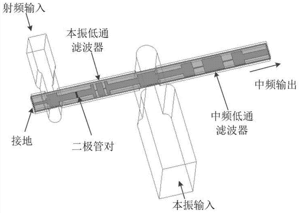
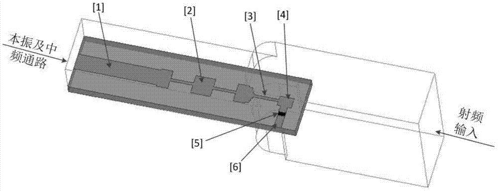
[0030] The invention proposes a novel millimeter-wave even-order harmonic mixer structure. The mixer structure concentrates the field in the middle of the waveguide and introduces fewer discontinuities. The structure is as figure 2 shown.

[0031] The frequency mixing microstrip substrate is placed in the same direction as the waveguide in the radio frequency waveguide, and placed in the center of the broadside of the waveguide. In this microstrip structure, the microstrip substrate extends into the RF waveguide The RF wavelength is about a quarter of the wavelength; the local oscillator and the intermediate frequency low-pass filter [2] are placed at the end face of the RF waveguide, which can not only effectively suppress the leakage of the RF signal, but also serve as an assembly location; reasonably design according to the local oscillator signa...


PUM


Abstract

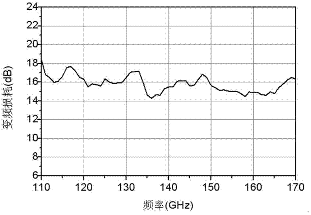
The invention discloses a millimeter-wave even harmonic mixer structure. The millimeter-wave even harmonic mixer structure comprises a frequency-mixing microstrip chip, an antiparallel diode pair, a local-oscillator low-pass filter and an intermediate-frequency low-pass filter, wherein the frequency-mixing microstrip chip is disposed in a radio-frequency waveguide in a direction identical with the waveguide and is disposed in the center of a broadside of the radio-frequency waveguide, the antiparallel diode pair is disposed at the tail end of the frequency-mixing microstrip chip, and the local-oscillator low-pass filter and the intermediate-frequency low-pass filter are arranged on the end face of the tail end of the radio-frequency waveguide, determine the length of the frequency-mixing microstrip chip disposed in the radio-frequency waveguide according to local oscillator signals and determine the width of a grounding end of the frequency-mixing microstrip chip according to the size of the antiparallel diode pair. The millimeter-wave even harmonic mixer structure has the advantages that radio-frequency signals can be well coupled to diodes, and when radio-frequency signals and the local oscillator signals are subjected to frequency mixing, the millimeter-wave even harmonic mixer structure is excellent in frequency conversion performance, high in consistency and broader in operation bandwidth.

Description

technical field [0001] The invention relates to the technical field of electronic communication, in particular to a millimeter-wave even-order harmonic mixer structure. Background technique [0002] As an important part of systems such as millimeter wave radar, guidance, communication and test instruments, the performance of the millimeter wave mixer determines the performance of the millimeter wave system to a certain extent. Therefore, millimeter-wave mixers have always been an important topic in millimeter-wave research. Although solid-state microwave devices have developed rapidly in recent years, for millimeter waves, as the frequency increases, the cost of the corresponding devices and systems also increases. At a certain mmWave frequency, the cost of generating a high-power mmWave signal at the corresponding frequency will also rise rapidly. Therefore, in order to reduce the cost as much as possible under the condition of meeting the application requirements of the ...

Claims


Application Information

Patent Timeline
IPC IPC(8): H03D7/16
Inventor 韦柳泰代秀尹沃良徐从玉
Owner THE 41ST INST OF CHINA ELECTRONICS TECH GRP
Learn More