
Micromachined ultrasonic transducer arrays with multiple harmonic modes

Active Publication Date: 2015-07-01
FUJIFILM DIMATIX
View PDF9 Cites 33 Cited by
  • Summary
  • Abstract
  • Description
  • Claims
  • Application Information

AI Technical Summary

Problems solved by technology

[0008] Another problem with conventional pMUT arrays is that mechanical coupling through substrate vibration and acoustic coupling between adjacent elements found in pMUT arrays can cause undesirable crosstalk between transducer elements

Method used


Image

  • Micromachined ultrasonic transducer arrays with multiple harmonic modes
  • Micromachined ultrasonic transducer arrays with multiple harmonic modes
  • Micromachined ultrasonic transducer arrays with multiple harmonic modes

Examples


Embodiment Construction

[0032] In the following description, numerous details are set forth, but it will be apparent to those skilled in the art that the invention may be practiced without these specific details. In some instances, well-known methods and devices are shown in block diagram form, rather than in detail, in order to avoid obscuring the invention. Reference to "an embodiment" throughout this specification means that a particular feature, structure, function, or characteristic related to the embodiment is included in at least one embodiment of the present invention. Thus, appearances of the term "in an embodiment" in various places throughout this specification do not necessarily refer to the same embodiment of the invention. Furthermore, the particular features, structures, functions or characteristics in one or more embodiments may be combined in any suitable manner. For example, a first embodiment may be combined with a second embodiment where the two embodiments are not specifically i...


PUM


Abstract

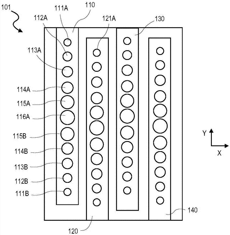
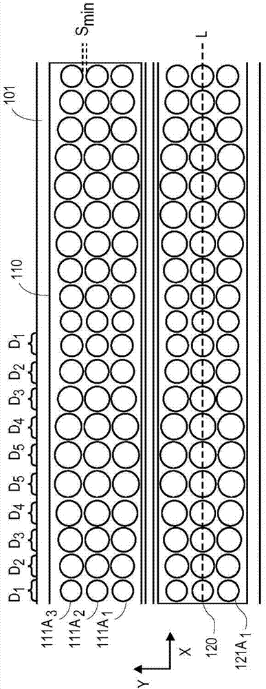
Micromachined ultrasonic transducer (MUT) arrays capable of multiple resonant modes and techniques for operating them are described, for example to achieve both high frequency and low frequency operation in a same device. In embodiments, various sizes of piezoelectric membranes are fabricated for tuning resonance frequency across the membranes. The variously sized piezoelectric membranes are gradually transitioned across a length of the substrate to mitigate destructive interference between membranes oscillating in different modes and frequencies.

Description

[0001] Cross References to Related Applications [0002] This application claims the title "PIEZOELECTRIC TRANSDUCER ARRAYS WITH 1 ST AND 2 ND HARMONIC MODES” U.S. Provisional Utility Patent Application, which is hereby incorporated by reference in its entirety for all purposes. [0003] This application is related to US Utility Patent Application entitled "ULTRA WIDE BANDWIDTH PIEZOELECTRIC TRANSDUCER ARRAYS" filed on October 9, 2012 and having application number 13 / 648,225. technical field [0004] Embodiments of the present invention relate generally to ultrasound transducers and, in particular, to micromachined ultrasound transducer (MUT) arrays. Background technique [0005] A typical ultrasonic transducer device includes a membrane capable of vibrating in response to a time-varying drive voltage to generate High frequency pressure waves. This high frequency pressure wave can propagate into other media. The same membrane can also receive pressure waves reflected ...

Claims


Application Information

Patent Timeline
Patent Type & Authority Applications(China)
IPC IPC(8): H04R19/00
CPCH01L41/0825H01L41/042H01L41/331B06B1/0629B06B1/0276B06B1/0622B06B1/0269H10N30/081H10N30/802H10N30/101A61B18/082
Inventor A·哈贾蒂
Owner FUJIFILM DIMATIX
Learn More