
A directional dust-exhausting and dust-reducing cover for a high-pressure down-the-hole drilling rig

A down-the-hole drilling rig and dust cover technology, which is applied in construction and other directions, can solve problems such as affecting air quality, long distances between different types of personnel, troublesome maintenance, etc., achieve strong anti-interference, improve the construction working environment, and reduce the spread of dust Effect

Inactive Publication Date: 2017-06-13
SHANDONG UNIV +2
View PDF8 Cites 2 Cited by
  • Summary
  • Abstract
  • Description
  • Claims
  • Application Information

AI Technical Summary

Problems solved by technology

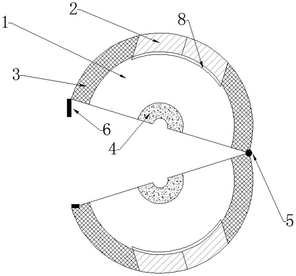
[0002] High wind pressure down-the-hole drilling rigs will generate a lot of dust during work. These dusts will affect the air quality and easily cause damage to the respiratory system of the staff. Therefore, a dust suppression and dust removal device is needed to settle the dust generated by drilling.
However, the existing dust collectors are expensive, bulky, and troublesome to maintain. Such sophisticated equipment is often not needed in the field environment, and the harsh working environment in the field makes the staff in serious floating dust, and the distance between different types of personnel is relatively long. This just needs a kind of low-cost, easy-to-load simple dust-reducing and dust-exhausting device

Method used


Image

  • A directional dust-exhausting and dust-reducing cover for a high-pressure down-the-hole drilling rig
  • A directional dust-exhausting and dust-reducing cover for a high-pressure down-the-hole drilling rig
  • A directional dust-exhausting and dust-reducing cover for a high-pressure down-the-hole drilling rig

Examples


Embodiment Construction

[0023] The present invention will be further described below in conjunction with the accompanying drawings and embodiments.

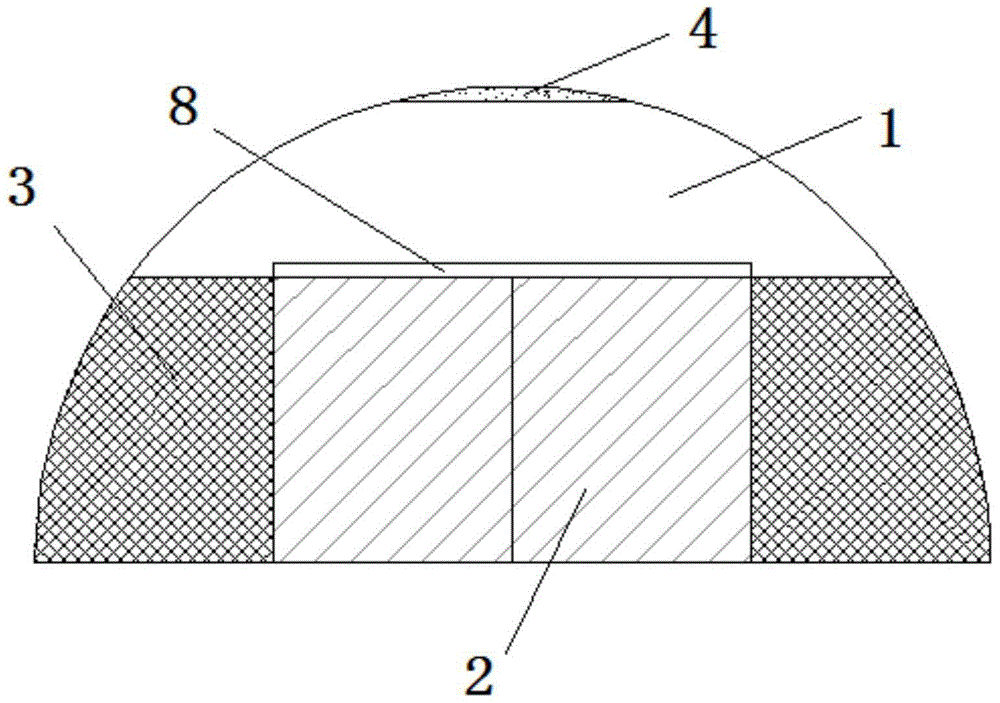
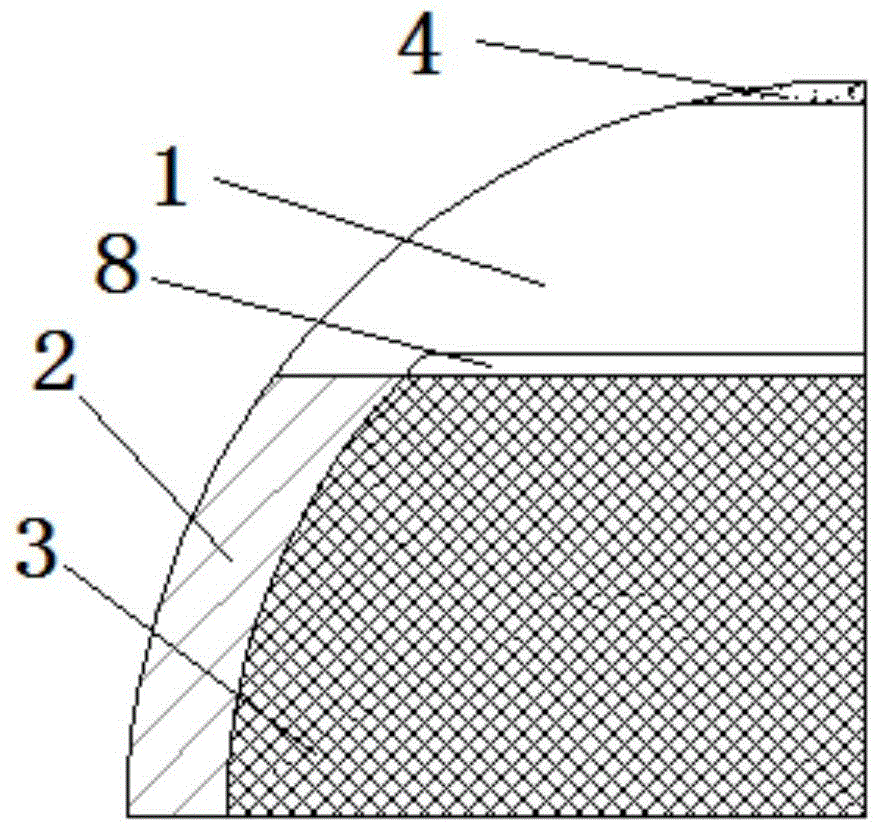
[0024] Such as Figure 1-Figure 5 As shown, the high wind pressure down-the-hole drilling rig directional dust discharge dust cover includes a dust cover, a filter screen 7, and a dust discharge directional plate 2. Dust with large particle size is filtered through the filter screen 7 , and fine dust and gas are directional discharged through the grid hollow part 3 under the constraint of the dust discharge directional plate 2 . The dust cover and the dust discharge directional plate 2 are corrosion-resistant metals, and the dust cover is two quarter spherical shells that are symmetrically closed. The lower part of the dust cover is a hollow grid part 3, the grid is a regular quadrilateral, and the upper part is an airtight part 1. There is a filter screen 7 inside the dust cover, which is attached to the inner wall of the dust cover with the air pres...


PUM


Abstract

The invention discloses an oriented dust-exhaust dust-fall cover of a high pneumatic DTH (Down-The-Hole) drill. The directional dust-exhaust dust-fall cover comprises a dust fall cover, a filter screen and a dust exhaust oriented plate; the dust-fall cover comprises left and right parts which are completely symmetric to each other, the upper part of the dust-fall cover is provided with an airtight piece, and a gridding hollow part is arranged all around the lower part of the dust-fall cover; the filer screen is arranged in the dust-fall cover, and the outer surface of the gridding hollow part covers the movable dust exhaust oriented plate; one sides of the left and right parts of the dust-fall cover are provided with a rotating shaft, the left and right parts are connected through the rotating shaft, and the other sides of the left and right parts of the dust-fall cover are provided with clamping bolts. According to the oriented dust-exhaust dust-fall cover provided by the invention, the effective control of the dust of the high pneumatic DTH drill can be realized, the strong anti-interference to wind can be realized, the dust diffusion can be realized, a worker can be prevented from sucking excessive dust, and the construction environment can be improved; the device is simple to operate, low in price and environmental-friendly in material, and is likely to be maintained, thereby being applicable to various drilling and construction environments, especially applicable to the operation of a windy wild drilling machine.

Description

technical field [0001] The invention belongs to the field of blasting engineering, and in particular relates to a dust collector for a drilling rig, in particular to a directional dust-exhausting and dust-reducing cover for a high-pressure down-the-hole drilling rig. Background technique [0002] High wind pressure down-the-hole drilling rigs will generate a lot of dust during work. These dusts will affect the air quality and easily cause damage to the respiratory system of the staff. Therefore, a dust suppression and dust removal device is needed to settle the dust generated by drilling. However, the existing dust collectors are expensive, bulky, and troublesome to maintain. Such sophisticated equipment is often not needed in the field environment, and the harsh working environment in the field makes the staff in serious floating dust, and the distance between different types of personnel is relatively long. This just needs a kind of cheap, easy-to-load dust-reducing and du...

Claims


Application Information

Patent Timeline
Patent Type & Authority Patents(China)
IPC IPC(8): E21B21/015
CPCE21B21/015
Inventor 张明伟徐帮树杨来华王者超赵香萍夏鹏陈诚
Owner SHANDONG UNIV
Learn More